Table of Contents
Advertisement
Instruction Manual
D200099X012
Fisher
249 Caged Displacer Sensors
™
Contents
. . . . . . . . . . . . . . . . . . . . . . . . . . . . . . . . .
. . . . . . . . . . . . . . . . . . . . . . . . . . . . .
. . . . . . . . . . . . . . . . . . . . . . . . . . . . . . . . .
. . . . . . . . . . . . . . . . . . . . . . . . .
. . . . . . . . . . . . . . . . . . . . . . . . . . . . . . . . .
. . . . . . . . . . . . . . . . . . . . . . . . . . .
. . . . . . . . . . . . . . . . . . . . . . . . . .
. . . . . . . . . . . . . . . . . . . . . . . . . . . . . . .
. . . . . . . . . . . . . . . . . . . . . . . . . . . . . . . . . . .
. . . . . . . . . . . . . . . . . . . . . . . . . . . . . . . . . . .
Introduction
Scope of Manual
This instruction manual includes maintenance and parts ordering information for 249 caged sensors.
Although a 249 sensor is usually shipped with attached controller or transmitter, this manual does not include
operation, installation, calibration, maintenance, and parts ordering information for the controller/transmitter or for
the complete unit. For this information, refer to the appropriate controller/transmitter instruction manual.
Note
Caged sensors have a rod and block shipping lock installed on each end of the displacer to protect the displacer in shipping, as
shown in figure 2. Remove these parts before installing the sensor to allow the displacer to function properly.
Do not install, operate or maintain a 249 sensor without being fully trained and qualified in valve, actuator, and
accessory installation, operation, and maintenance. To avoid personal injury or property damage, it is important to
www.Fisher.com
. . . . . . . . . . . . . . . . . . . . .
. . . . . . . . . . . . . .
. . . . . . . . . . . . . . .
. . . .
. . . . . . . . . . . . . . . . . . . .
. . . . . . . . . . . . . . . .
. . . . . . . . . . . . . . . . . . .
. . . .
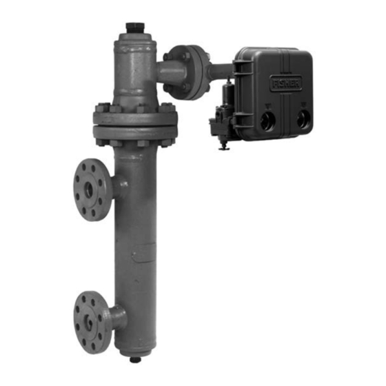
Figure 1. Fisher 249B Sensor with 2500 Controller
1
1
2
3
4
4
5
6
7
8
9
10
11
12
12
12
13
13
W3121-3
249 Caged Sensors
April 2017
Advertisement
Table of Contents

Related Manuals for Fisher 249


Summary of Contents for Fisher 249
-
Page 1: Table Of Contents
2. Remove these parts before installing the sensor to allow the displacer to function properly. Do not install, operate or maintain a 249 sensor without being fully trained and qualified in valve, actuator, and accessory installation, operation, and maintenance. To avoid personal injury or property damage, it is important to... -
Page 2: Description
Description 249 sensors are designed to measure liquid level, interface level, or density/specific gravity inside a vessel. A torque tube assembly (figure 3) and displacer provide an indication of liquid level, interface level, or density/specific gravity. The torque tube assembly consists of a hollow torque tube with a shaft welded inside it at one end and protruding from it at the other end. -
Page 3: Type Number Description
D 249K—CL900 or 1500 steel cage with flanged connections only. D 249L—CL2500 steel cage with flanged connections only. The cage head on all of the 249 constructions may be rotated to any of the eight alternate positions shown in figure 7. Connection sizes are either NPS 1‐1/2 or 2. -
Page 4: Educational Services
The Parts List section shows some 249 sizes by construction, standard displacer lengths, and standard materials and table 1 contains displacer and torque tube materials. However, 249 parts are available in a wide variety of materials of construction, part dimensions, and other specifications. Contact your... -
Page 5: Cleaning The Cage
D Drain the process liquid from the vessel. D Shut off any electrical or pneumatic input to the controller or transmitter attached to the 249 sensor and vent any pneumatic supply pressure. Remove the controller or transmitter from the torque tube arm (key 3). Take care not to damage the torque tube assembly (key 9) inside the torque tube arm. -
Page 6: Removing The Displacer And Stem
Instruction Manual 249 Caged Sensors April 2017 D200099X012 CAUTION When removing a sensor from a cage, the displacer may remain attached to the displacer rod and be lifted out with the cage head when the cage head is removed. If separating the displacer and displacer rod before removing the cage head, remove the cotter spring (key 11). -
Page 7: Replacing The Displacer, Cotter Spring, Stem End Piece, And Displacer Spud
D Drain the process liquid from the vessel. D Shut off any electrical or pneumatic input to the controller or transmitter attached to the 249 sensor and vent any pneumatic supply pressure. Remove the controller or transmitter from the torque tube arm. -
Page 8: Replacing The Displacer Rod/Driver Assembly
Instruction Manual 249 Caged Sensors April 2017 D200099X012 CAUTION If the displacer is to be disconnected from the displacer rod before being removed from the cage, provide a suitable means of supporting the displacer to prevent it from dropping into the cage and being damaged. -
Page 9: Replacing The Torque Tube
Instruction Manual 249 Caged Sensors D200099X012 April 2017 Place a screwdriver blade in the slots of the positioning plate and outer tube end as shown in figure 6. Slowly turn the positioning plate to release its lug from the torque tube arm. Then carefully turn the plate back to allow the displacer to come to rest, and slip the other lug of the plate from its slot in the outer tube end. -
Page 10: Changing Cage Head Position
Instruction Manual 249 Caged Sensors April 2017 D200099X012 1. After following the proper procedure to remove the cage head and the displacer from the cage, move the sensor assembly to a suitable maintenance area. CAUTION Support the sensor assembly to avoid damage to the displacer, displacer stem, displacer rod assembly, and associated parts. -
Page 11: Replacing The Torque Tube Arm And Changing The Mounting
D Drain the process liquid from the vessel. D Shut off any electrical or pneumatic input to the controller or transmitter attached to the 249 sensor and vent any pneumatic supply pressure. Remove the controller or transmitter from the torque tube arm. -
Page 12: Simulation Of Process Conditions For Calibration Of Fisher Level Controllers And Transmitters
Simulation of Process Conditions for Calibration of Fisher Level Controllers and Transmitters Contact your Emerson sales office or Local Business Partner for information on obtaining the Supplement to 249 Sensor Instruction Manuals—Simulation of Process Conditions for Calibration of Fisher Level Controllers and Transmitters (D103066X012), or visit our website at Fisher.com. -
Page 13: Parts Kits
Use only genuine Fisher replacement parts. Components that are not supplied by Emerson Automation Solutions should not, under any circumstances, be used in any Fisher instrument. Use of components not supplied by Emerson Automation Solutions may void your warranty, might adversely affect the performance of the instrument, and could cause personal injury or property damage. - Page 14 Instruction Manual 249 Caged Sensors April 2017 D200099X012 Figure 8. Fisher 249 Sensor Construction SECTION A‐A DETAIL OF CL250 S2, S3, OR S4 CONNECTIONS 30A1913‐B 30A7422‐B...
- Page 15 (S) and flanged (F). Four connection configurations 249L only are available: Tube End Gasket D 1, top and bottom of cage 249, 249B, 249C, 249K, and 249L D 2, top and lower side of cage Graphite‐stainless steel D 3, side of cage only Outer End Gasket...
- Page 16 249 Caged Sensors Instruction Manual April 2017 D200099X012 Figure 10. Fisher 249C Sensor Construction SECTION A‐A DETAIL OF STYLE 3 OR 4 CONNECTIONS 30A7425‐B 30A7428‐B Description Description Pipe Plug Bolt Stud , steel B7 (4 req'd) For 249B, styles 2, 3, steel For 249B, 249C...
- Page 17 Instruction Manual 249 Caged Sensors D200099X012 April 2017 Figure 11. Fisher 249K Sensor Construction SECTION A‐A 30A7429‐D Description Description Cap Screw , steel B7 (8 req'd) Hex Nut , steel For 249 For 249 CL125 CL250 (8 req'd) CL250 For 249B (16 req'd) For 249C (8 req'd)
- Page 18 April 2017 D200099X012 Description Description Pipe Plug For 249, malleable cast iron 1‐1/2 NPT (styles S2, S3, S4) (2 req'd) 2 NPT (style S2, S3, & S4) For 249B, steel (styles S3, S4) For 249C, S31600 (styles S3, S4) Notes For 249K, steel (styles S3, S4)
-
Page 19: D200099X012 April
Instruction Manual 249 Caged Sensors D200099X012 April 2017 Figure 12. Fisher 249L Sensor Construction SECTION A‐A 50A7430‐C... - Page 20 Responsibility for proper selection, use, and maintenance of any product remains solely with the purchaser and end user. Fisher is a mark owned by one of the companies in the Emerson Automation Solutions business unit of Emerson Electric Co. Emerson Automation Solutions, Emerson, and the Emerson logo are trademarks and service marks of Emerson Electric Co.
Need help?
Do you have a question about the 249 and is the answer not in the manual?
Questions and answers