
Related Manuals for Miller Pro-Hobby Series


Summary of Contents for Miller Pro-Hobby Series
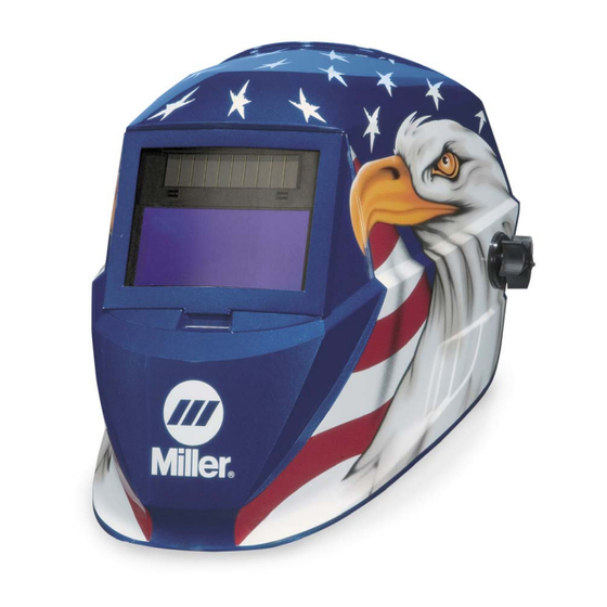
- Page 1 OM-231 425-A 2006−10 ® Auto-Darkening Helmets Pro-HobbytSeries To help us serve you better, go to www.MillerWelds.Com/Helmet/Reg/...
-
Page 2: Table Of Contents
TABLE OF CONTENTS SECTION 1 − SAFETY PRECAUTIONS − READ BEFORE USING ..... . . 1-1. Symbol Usage ............. 1-2. -
Page 3: Section 1 − Safety Precautions − Read Before Using
SECTION 1 − SAFETY PRECAUTIONS − READ BEFORE USING Y Warning: Protect yourself and others from injury — read and follow these precautions. 1-1. Symbol Usage Means Warning! Watch Out! There are possible hazards with this procedure! The possible hazards are shown in the ad- joining symbols. -
Page 4: Section 2 − Specifications
SECTION 2 − SPECIFICATIONS Specification Variable Shade Model Fixed Shade No. 10 Model Viewing Field 95 x 40mm (3.75 x 1.55 in) 95 x 35mm (3.75 x 1.375 in) Reaction Time (XLi) 0.000083sec (1/12,000) 0.000277sec (1/3,600) Available Shades Darkened State: No. 8 − No. 12 Darkened State: No. -
Page 5: Section 3 − Operating Instructions
SECTION 3 − OPERATING INSTRUCTIONS 3-1. Helmet Controls Two different lens assemblies are shown. Refer to the illustration that matches the lens on your hel- met. Variable Shade Model On Button (See Section 3-2) Low Battery Indicator (See Section 3-2) Lens Delay Control (See OPEN LOCK... -
Page 6: On Button And Low Battery Indicator (Variable Shade Models Only)
3-2. On Button And Low Battery Indicator (Variable Shade Models Only) On Button Press button to turn on lens and be- gin welding. The lens will automati- cally darken twice and then return to the light state. The lens will automatically turn Off (clear state −... -
Page 7: Variable Shade Control (No. 8 − 12) (Variable Shade Models Only)
3-4. Variable Shade Control (No. 8 − 12) (Variable Shade Models Only) Variable Shade Control (No. 8 − 12) Use the control to adjust the lens shade in the darkened state. Use the table below to select proper shade control setting based on your welding process. -
Page 8: Sensitivity Control (Variable Shade Models Only)
3-5. Sensitivity Control (Variable Shade Models Only) Sensitivity Control Use control to make the lens more re- sponsive to different light levels in vari- ous welding processes. Use a Mid- Range or 30−50% sensitivity setting for most applications. It may be necessary to adjust helmet sensitivity to accommodate different lighting conditions or if lens is flashing On and Off. -
Page 9: Section 4 − Adjusting Headgear
SECTION 4 − Adjusting Headgear There are four headgear ad- justments: headgear top, tightness, distance adjust- ment, and angle adjustment. Headgear Top Adjustment Adjusts headgear for proper depth on the head to ensure cor- rect balance and stability. Headgear Tightness Adjustment Adjusts headgear for a secure fit. -
Page 10: Section 5 − Replacing The Lens Covers
SECTION 5 − REPLACING THE LENS COVERS 5-1. Replacing Outside Lens Cover Y Never use the auto-darkening lens without the inside and outside lens covers properly installed. Welding spatter will damage the auto-darkening lens and void the warranty. Outside Lens Cover Frame Lens Gasket Remove lens cover frame by grasp-... -
Page 11: Replacing Inside Lens Cover
5-2. Replacing Inside Lens Cover Y Never use the auto-darkening lens without the inside and out- side lens covers properly installed. Welding spatter will damage the auto-darkening lens and void the warranty. inside Lens Cover Remove the inside lens cover by pry- ing the lens up at the thumbnail open- ing located at the top center of the lens cover. -
Page 12: Section 6 − Replacing The Battery
SECTION 6 − REPLACING THE BATTERY 6-1. Variable Shade Models Battery Cover Slide cover to left and remove batter- ies. Install two AAA lithium batteries and replace cover. AAA BATTERY OPEN LOCK 804 792 6-2. Fixed Shade No. 10 Models Solar Cell (Internal) Fixed shade models are powered by a rechargeable, non-replaceable so-... -
Page 13: Section 7 − Installing Optional Magnifying Lens
SECTION 7 − INSTALLING OPTIONAL MAGNIFYING LENS Outside Lens Cover Frame Optional Magnifying Lens Remove lens cover frame by grasping the outside corners and pulling the frame away from the hel- met. Remove the auto-darkening lens assembly by gently lifting the hel- met lip above the assembly and pushing assembly free of the re- taining brackets. -
Page 14: Section 8 − Maintenance
SECTION 8 − MAINTENANCE Never use solvents or abrasive cleaning detergents. Do not immerse the lens assembly in water. The helmet requires little maintenance. However, for best performance clean after each use. Using a soft cloth dampened with a mild soap and water solution, wipe the cover lenses clean. -
Page 15: Section 10 − Parts List
SECTION 10 − PARTS LIST Miller 804 796 Figure 10-1. Pro-Hobby Auto-Darkening Welding Helmet OM-231 425 Page 13... - Page 16 ..Bag Helmet, Miller .......
- Page 17 NOTES OM-231 425 Page 15...
- Page 18 NOTES OM-231 425 Page 16...
-
Page 19: Section 11 − Limited Warranty
LIMITED WARRANTY – Subject to the terms and conditions below. Miller Electric Mfg. Co., Appleton, Wisconsin, warrants to its original retail pur- chaser that the new Miller equipment sold after the effective date of this limited warranty is free of defects in material and workmanship at the time it is shipped by Miller. - Page 20 Visit our website at www.MillerWelds.com ® Miller Electric Mfg. Co. An Illinois Tool Works Company 1635 West Spencer Street Appleton, WI 54914 USA © PRINTED IN USA 2006 Miller Electric Mfg. Co.
Need help?
Do you have a question about the Pro-Hobby Series and is the answer not in the manual?
Questions and answers