Table of Contents
Advertisement
© Copyright 2017
EVERTZ MICROSYSTEMS LTD.
5292 John Lucas Drive
Burlington, Ontario
Canada L7L 5Z9
Phone:
+1 905-335-3700
Sales:
sales@evertz.com
Tech Support: service@evertz.com
Web Page:
http://www.evertz.com
Version 1.0, January 2017
The material contained in this manual consists of information that is the property of Evertz Microsystems and is intended solely for the use of
purchasers of the 5700MSC Master Clock product. Evertz Microsystems expressly prohibits the use of this manual for any purpose other than
the operation of the 5700MSC Master Clock product. Due to on going research and development, features and specifications in this manual
are subject to change without notice.
All rights reserved. No part of this publication may be reproduced without the express written permission of Evertz Microsystems Ltd. Copies
of this manual can be ordered from your Evertz dealer or from Evertz Microsystems.
Model 5700MSC
Master Clock System
Quick Start Guide
Fax: +1 905-335-3573
Fax: +1 905-335-7571
Advertisement
Table of Contents

Subscribe to Our Youtube Channel
Related Manuals for evertz 5700MSC


Summary of Contents for evertz 5700MSC
-
Page 1: Quick Start Guide
Version 1.0, January 2017 The material contained in this manual consists of information that is the property of Evertz Microsystems and is intended solely for the use of purchasers of the 5700MSC Master Clock product. Evertz Microsystems expressly prohibits the use of this manual for any purpose other than the operation of the 5700MSC Master Clock product. - Page 2 This page left intentionally blank...
-
Page 3: Important Safety Instructions
IMPORTANT SAFETY INSTRUCTIONS The lightning flash with arrowhead symbol within an equilateral triangle is intended to alert the user to the presence of uninsulated “Dangerous voltage” within the product’s enclosure that may be of sufficient magnitude to constitute a risk of electric shock to persons. The exclamation point within an equilateral triangle is intended to alert the user to the presence of important operating and maintenance (Servicing) instructions in the literature accompanying the product. - Page 4 WARNING Changes or Modifications not expressly approved by Evertz Microsystems Ltd. could void the user’s authority to operate the equipment. Use of unshielded plugs or cables may cause radiation interference. Properly shielded interface...
- Page 5 Evertz products are for informational use only and are not warranties of future performance, either expressed or implied. The only warranty offered by Evertz in relation to this product is the Evertz standard limited warranty, stated in the sales contract or order confirmation form.
- Page 6 Model 5700MSC Master Clock System This page left intentionally blank Page - ii Revision 1.0...
-
Page 7: Table Of Contents
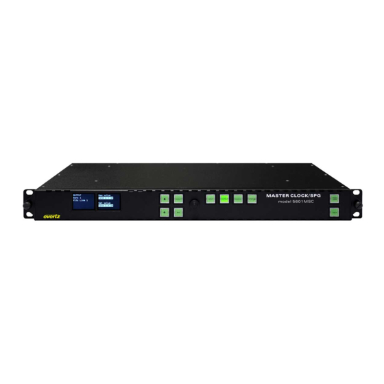
1.10. CONFIGURING THE TIME OUTPUTS ................. 5 1.11. FINAL STEPS OF SET UP AND SECURING ALL CONNECTIONS ........6 1.12. ACCESS CONTROL ......................6 Figures Figure 1-1: 5700MSC Front Panel........................1 Figure 1-2: 5700MSC Rear Panel View ......................4 Page - iii Revision 1.0... - Page 8 Model 5700MSC Master Clock System This page left intentionally blank Page - iv Revision 1.0...
-
Page 9: Overview
When re-installing the front panel be sure to fully tighten the thumb screws. When AC power is applied to the 5700MSC and the power supplies are switched on, the unit will start up automatically. The front panel should become operative within approximately 30 seconds. -
Page 10: Configuring The Ethernet Ports
Press the GENERAL button on the front panel to access the general setup menu. This menu can be used to configure the two Ethernet ports on the 5700MSC. Both the GigE 1 port and the GigE 2 port are used for SNMP monitoring and control of the unit. -
Page 11: Selecting And Connecting Time References
1, or frame reference 2. The frequency stability of the 5700MSC will be only as good as that of the reference input. The phase of the outputs will be aligned to that of the reference input. -
Page 12: Checking The Status Of The Unit
Master Clock System • None – The 5700MSC will not acquire time from any outside source. The time and date must be manually entered using the front panel in the GENERAL menu. The high frequency stability of the unit and battery backup will ensure the 5700MSC keeps fairly accurate time. -
Page 13: Configuring The Sync Outputs
1.8. CONFIGURING THE SYNC OUTPUTS The sync outputs of the 5700MSC are configured in the OUTPUT menu, accessed by pressing the OUTPUT button. All sync outputs are derived from the master oscillator and will be locked in frequency and phase. The sync outputs are all programmable to output several different sync types and can be phased independently from each other. -
Page 14: Final Steps Of Set Up And Securing All Connections
Phillips mounting screw. The GPS D-Sub connector on the back of the unit should be secured to the 5700MSC using mounting screws. The AC power cords can be fixed to the unit using the retaining clips provided.
Need help?
Do you have a question about the 5700MSC and is the answer not in the manual?
Questions and answers