Table of Contents
Advertisement
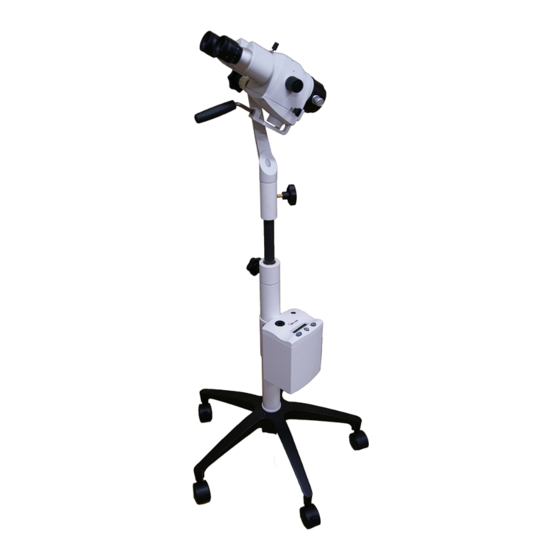
COLPOSCOPE 935
USER'S MANUAL
Including installation instructions for all mounting
options
This document is property of Seiler Instrument & Mfg. Co., Inc.
No part of this manual should be reproduced or transmitted without the expressed written consent being
obtained. All the figures and images appearing in this manual are for illustration purposes only and
may vary according to the version of the device purchased. The information contained in this manual is
subject to change without notice. Please contact Seiler whenever additional information is needed.
This device is restricted to the sale and the use by authorized and trained personnel.
MEDICAL DIVISION
Advertisement
Table of Contents

Related Manuals for Seiler COLPOSCOPE 935


Summary of Contents for Seiler COLPOSCOPE 935
- Page 1 All the figures and images appearing in this manual are for illustration purposes only and may vary according to the version of the device purchased. The information contained in this manual is subject to change without notice. Please contact Seiler whenever additional information is needed. MEDICAL DIVISION...
-
Page 2: Table Of Contents
Table of Contents INTRODUCTION ..........................4 INTENDED USE ........................... 5 PRESENTATION AND USE ......................... 5 COLPOSCOPE FLOOR STAND ......................5 THE COLPOSCOPE HEAD ......................... 6 CLEANING ............................6 PREPARATION FOR USE ........................7 COLPOSCOPE USE ..........................8 OPTICAL AND FIELD MAGNIFICATION TABLE ................9 TECHNICAL DATA .......................... - Page 3 SYMBOLS USED IN THIS MANUAL OR DEVICE ...............25-26 WARNINGS ............................27 WARRANTIES ..........................28-29 CERTIFICATE OF CONFORMITY ..................... 30 DECLARATION OF CONFORMITY ....................31 - 3 -...
-
Page 4: Introduction
To Our Valued Professionals, On behalf of the Seiler Medical Division, I would like to thank you for your recent purchase. We stand by our products and are thrilled that when choosing one of the most important aspects of your practice, you chose us. -
Page 5: Intended Use
Intended use The Seiler Colposcope is intended to provide magnified visualization of the tissues of the vulva, vagina, cervix, and anogenital area. It is used to evaluate these tissues, select areas for biopsy, as necessary, and to facilitate related procedures, e.g., LEEP, conization, etc. -
Page 6: The Colposcope Head
Colposcope Head optic pod components Eyepieces Binocular Head Thumb Screw Magnification Turret Objective Lens Fine Focus Knob Handle Green Filter (Push/Pull Knob) cleaning The Objective, at the bottom of the Colposcope body, may be exposed to blood and other bodily fluids. Spots on the objective dim the passage of light. -
Page 7: Preparation For Use
PREPARATION FOR USE INSPECT AND CLEAN Before each use, inspect the colposcope including power cable, base, casters, lightsource and light guide. Do not use the colposcope if any of the components are damaged, missing, or are not secure. Verify that the light guide is properly installed in both the lightsource and the optic pod. Clean and disinfect the colposcope before and after each use. -
Page 8: Colposcope Use
COLPOSCOPE USE Prepare the colposcope for use following the PREPARATION FOR USE instructions. Turn the light source on and set the desired brightness following the instructions in the LED LIGHT SOURCE section. Turn the lightsource off while the colposcope is not being used. POSITION THE COLPOSCOPE Position the colposcope for use at a distance approximately equal to the objective lens focal length which is engraved on the external face of the objective. -
Page 9: Optical And Field Magnification Table
optical and field magnification table The optical magnifications achieved with the Colposcope are determined by 3 variables: the objective focal distance, the position of the Magnification Selector, and by the eyepiece used. The table shows the optical magnification and the observed field diameters, in millimeters, depending on those variables. -
Page 10: Led Light Source
Seiler’s LED Heliolux is intended for use in a professional healthcare facility environment. Seiler’s LED Heliolux is only to be used with light cables having the exact mating profile necessary to ensure proper coupling of the light source to the light cable. -
Page 11: Federal Law May Govern The Use Of This Device
1.3 FEDERAL LAW MAY GOVERN THE USE OF THIS DEVICE Federal law restricts the use of certain medical devices. Seiler’s LED Heliolux is intended to be a sub-com- ponent of a medical device (system). Such device (system) may be regulated by Federal Law. It is the user’s responsibility to ensure that the device is being used in a manner appropriate with Federal Law. -
Page 12: Manufacturer's Declaration
1.5 MANUFACTURER’S DECLARATION Version Type Guidance EN55011 2009 Emissions Pass 2010 Emissions Pass CISPR 11 2009 Emissions Group 1, Class B Pass 2010 Emissions Pass EN 61000-3-2 2014 Harmonic Current Pass IEC 61000-3-2 2014 Harmonic Current Class A Pass EN 61000-3-3 2013 Flicker Pass... -
Page 13: Symbols Used In This Manual Or On The Device
Version Type Guidance IEC 61000-4-11 2004 Voltage Dips and Interrupts 0 % UT; 0,5 cycle At 0°, 45°, 90°, 135°, 180°, 225°, 270° and 315° 0 % UT ; 1 cycle 70 % UT ;25/30 cycles Single phase: at 0° 0% UT;... -
Page 14: Hazards Associated With Improper Installation
3.0 HAZARDS ASSOCIATED WITH IMPROPER INSTALLATION Failure to read and understand Personnel tasked with installation of the device should fully familiarize these Instructions for Use is themselves with the contents of these Instructions for Use and only hazardous. attempt installation or maintenance of the device once they have a complete understanding of these Instructions. -
Page 15: Installation Instructions/Preparing And Siting
STOP and arrange for qualified maintenance personnel to inspect. If, at any point, you suspect something is wrong then terminate installation / operation of the Seiler’s • LED Heliolux by pressing the MAINS ON/OFF (blue switch with international 0/1 designation). The blue light should be off. -
Page 16: Installation Instructions
3.2 INSTALLATION INSTRUCTIONS Inspect shipping containers for damage. In event damage is discovered STOP and arrange for • qualified maintenance personnel to inspect. • Mount the illuminator per the system level documentation and in accordance with the hazard mitigation instructions. •... -
Page 17: Use Instructions
STOP and arrange for qualified maintenance personnel to inspect. If, at any point, you suspect something is wrong then terminate operation of the Seiler’s LED Heliolux • by pressing the MAINS ON/OFF (blue switch with international 0/1 designation). The blue light should be off. -
Page 18: Hazards Associated With Improper Use
STOP and arrange for qualified maintenance personnel to inspect. If, at any point, you suspect something is wrong then terminate operation of the Seiler’s LED Heliolux • by pressing the MAINS ON/OFF (blue switch with international 0/1 designation). The blue light should be off. - Page 19 Read the rear label at angle under 10 degrees from distance less than 0.25 meter with minimum • lighting of 1500 lux. • Confirm device has been properly installed. Appropriate light cable is installed at both ends (Seiler’s LED Heliolux and device requiring • illumination). Hospital grade power cable is properly installed. •...
-
Page 20: Cleaning Instructions
6.0 CLEANING INSTRUCTIONS Seiler’s LED Heliolux is not designed to resist spillage from any direction. Keep the device dry and free from spillage at all times. To clean: • Do not use any of the following for cleaning: Full strength bleach. -
Page 21: Front Panel
8.2 FRONT PANEL CAMERA POWER Jack - For installation 12 VDC at 500 ma max of LIGHT CABLE 8.3 rear panel Exhaust Fan IFC Mains Power Inlet Factory Connector (Do Not Use) Mains ON/OFF Switch - 2 1-... -
Page 22: Controls
8.4 controls CONTROL PAD LCD DISPLAY There are (3) basic controls. The top line of the display identifies the company or brand. An UP button for increasing intensity. The bottom line displays status as well as dim- A DOWN button for decreasing intensity. ming level. -
Page 23: Other Specifications
Should your product prove to have such defects within three years of the shipment. Seiler Instrument will repair or replace the product or component part with- out charge. Should your LED Light Source product(s) need servicing under this warranty, please contact, Seiler Instru- ment return authorization documentation. -
Page 24: Return Policy
RETURN POLICY Buyer must obtain a Return Material Authorization (RMA) Number from Seller prior to shipping any Product back to Seller. All Re- turns to be sent prepaid by Buyer. At the discretion of the Seller, unused and undamaged Standard Products may, under certain circumstances, be accepted back for credit or exchange. -
Page 25: Symbols Used In This Manual Or Device
SYMBOLS USED IN THIS MANUAL OR DEVICE MARKING/SYMBOL MEANING Symbol for “Consult instructions for use” or “Consult operating instructions.” Symbol for “Caution, consult accompanying documents” or “Attention, see instructions for use.” Symbol for “Caution Hot Surface”. This symbol cautions that surface should not be touched as it may be hot and could be a burn hazard. - Page 26 Symbol for “Serial Number.” This symbol shall be followed by, or above, the manufacturer’s serial number. Symbol for “Authorized Representative in the European Community.” This symbol shall be adjacent to the name and address of the authorized representative in the European Community.
-
Page 27: Warnings
WARNINGS This manual contains critical information regarding safe handling, use and care of this system. Harm to personnel or property damage could result if all instructions are not followed. Hazard Description Hazard Mitigation Failure to read and understand these Personnel tasked with use and Instructions for Use is hazardous and maintenance of the device should may result in injury to personnel. -
Page 28: Warranties
Except as set forth in this Three (3) Year International Warranty, Seiler Instrument Company (“SIC”) hereby warrants that each Seiler microscope product manufactured and/or sold by SIC shall be free from defects in materials and workmanship under normal use and service for three years. International Warranty includes mechanics, optics, and hardware (such as casters, knobs, tension band). -
Page 29: Warranties
Except as set forth in this Limited Lifetime Warranty, Seiler Instrument Company (“SIC”) hereby warrants that each Seiler microscope product manufactured and/or sold by SIC shall be free from defects in materials and workmanship under normal use and service for the life of the product. Lifetime Warranty includes mechanics, optics, hardware (such as casters, knobs, tension band). -
Page 30: Certificate Of Conformity
- 3 0 -... -
Page 31: Declaration Of Conformity
- 3 1 -... - Page 32 MEDICAL DIVISION 3433 Tree Court Industrial Blvd. St. Louis, Missouri 63122 Toll Free: (800) 489-2282 Local: (314) 968-2282 Email: micro@seilerinst.com www.seilerinst.com Atlantico Systems Ltd. 34 Oldfield Kingston, Galway Ireland www.atlanticosystems.com MED8011 Rev.0 4.9.18...
Need help?
Do you have a question about the COLPOSCOPE 935 and is the answer not in the manual?
Questions and answers
the green Filter when pulled only lights up 1/4 of scope lens
The manual does not provide specific reasons for the green filter only lighting up 1/4 of the scope lens when pulled. However, possible causes could include partial misalignment of the filter mechanism, incorrect positioning of the Push/Pull Knob, or an obstruction in the optical path. Checking the filter's position and ensuring proper alignment may help resolve the issue.
This answer is automatically generated