Table of Contents
Advertisement
Quick Links
Advertisement
Table of Contents

Related Manuals for GPG P260

Summary of Contents for GPG P260
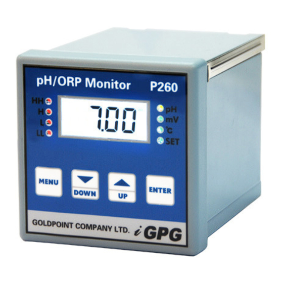
- Page 1 P260 pH / REDOX MONITOR OPERATION GUIDE...
-
Page 2: Table Of Contents
CONTENTS INTRODUCTION ..… FEATURES AND TECHNICAL SPECIFICATIONS Features.. Technical Specifications ..INSTALLATION Dimension Panel Cut-out ..Connection..MENU STRUCTURE SETTING AND OPERATION.. User Interface and Description ..Parameter Setting and Operation..5.2.1 Set Alarm 5.2.2 Calibration .. -
Page 3: Introduction
P260 Intelligent On-line PH / REDOX(ORP) Monitor 1. INTRODUCTION The P260 is a microprocessor controlled pH and Redox measurement instrument. The unit utilizes a multifunction LCD to display readings and provide feedback to the user. It is available with different option to provide fully configurable control, alarm and feedback with up to two relays and 0/4-20mA current output sources. -
Page 4: Installation
(6) Alarm Output:Two relays outputs (250V/10A) ,full range with hysteresis adjustable (7) Current output:DC 4~20mA,Opto-isolated outputs,( 750Ω Max. load) (8) Ambient Operating temperature:-10~+55℃ (9) Humidity:≤95% (10) Power supply:AC110 ~220V,50~60Hz 3. INSTALLATION The panel-mounting version is designed to be flush mounted and sealed in a square cut-out in a panel, and is held in place with the two screw clamps provided. -
Page 5: Dimension
Dimensions Figure 2 : overall dimensions panel-mounting 3.2 Panel Cut-out Figure 3: cut-out diagram ¨The panel cut-out for mounting the unit should be 92 mm x 92 mm (+1.0– 0.0). ¨Two screw clamps are supplied and are fitted from the back of the instrument... -
Page 6: Connection
3.3 Connection Figure 4: connection terminals diagram Connection terminals wiring directions: pH or redox sensor central line Spare Temperature sensor(1) Temperature sensor(2)/ pH or redox sensor shield 4~20mA Output (+) 4~20mA Output (-) Spare Spare Spare (10) High/Low alarm relay(Common) (11) Spare (12) High alarm relay(N/O, normally open) (13) Low alarm relay(N/O, normally open) -
Page 7: Menu Structure
(N) Power supply terminal: Connect the power supply phase ★ CAUTION ! : The specified performance of the P260 is entirely dependent on correct installation. For this reason, the installer should thoroughly read the instructions before attempting to make any electrical connections to the unit. - Page 8 Auto calibration 7.00pH Auto Return Auto calibration 9.18pH Auto Return Auto calibration 10.0pH Auto Return Manual calibration low pH value Manual calibration mid pH value Manual calibration high pH value Manual calibration low mV value Manual calibration zero mV value Manual calibration high mV value Auto calibration low Temp.
- Page 9 Set Manual temperature compensation value T he input for the current ( output is pH/ORP ) ( T he input for the current output is temperature ) Set current output start value Set current output end value Set input start value for the current output Set input end value for the current output...
-
Page 10: Setting And Operation
(Measure pH) (Measure redox) (Measure temperature) Restore factory setting Auto Return 5. SETTING AND OPERATION 5.1 User Interface and Description Figure 5: front panel diagram Front panel description: (1) HH alarm light,(spare) (2) H alarm light,Under the conditions of setting high alarm, when the measured pH value of the solution is higher than the value of High alarm, the H alarm light will be turned on and the high relay (N/O) close;... -
Page 11: Parameter Setting And Operation
value of High alarm, furthermore lower than the hysteresis, the H alarm light will be turned off and the high relay (N/O) open. (3) L alarm light,Under the conditions of setting low alarm, when the measured pH value of the solution is lower than the value of low alarm, the L alarm light will be turned on and the low relay (N/O) close;... -
Page 12: Set Alarm
Indicates that the instrument is working in the measurement state. Figure 6 measurement state 5.2.1 Set Alarm The P260 monitor has two alarm outputs designated high alarm(H) and low alarm(L). The alarm value and alarm hysteresis can be set within the currently selected measuring range. - Page 13 Alarm Relay During normal operation when the alarm is not active, the alarm output will be in its NORMAL condition, the N/O (normal open) contact will be open. When the alarm is active, the alarm output will be in its ALARM condition and therefore the N/O contact will be closed.
-
Page 14: Calibration
5.2.2 Calibration Calibration Intervals The P260 Monitor and Sensor combination once calibrated will require calibration checking/recalibration at 3-6 monthly intervals, however this does depend on the application. The calibration of the instrument can be effected by seasonal variations in the measured effluent, however only knowledge of the application can determine the re-calibration interval required. - Page 15 P7.00 Auto calibrate pH=7.00 Use pH=7.00 buffer to calibrate P9.18 Auto calibrate pH=9.18 Use pH=9.18 buffer to calibrate P10.0 Auto calibrate pH=10.0 Use pH=10.0 buffer to calibrate *Note: The above solution temperature is 25℃ General sensor calibration, two-point calibration method and three-point calibration method can be use as needed.
- Page 16 *Note: The above solution temperature is 25℃ 5.2.2.3 C0、 、 、 、 C100—temperature calibration P260 has temperature measurement function, for the automatic temperature compensation, and also can be displayed on the monitor. Temperature calibration requires a high and a low constant temperature environment.
-
Page 17: Temperature Compensation
5.2.3 Temperature Compensation 5.2.3.1 CC—auto/manual temperature compensation switch P260 has Auto and manual temperature compensation function. The user can select between two modes of compensation by the CC in the ENTER menu. Press into CC and display CC0 or CC1. CC0 is Auto temperature compensation, CC1 is manual temperature compensation. -
Page 18: Set Current Output
Manual temperature setting Range: 5.2.4 Set Current Output P260 has one 4~20mA current output. The user can select the input source: pH/ORP or temperature. And the current output can be set work over the whole range of the input source. - Page 19 ENTER Press to switch it, then Press to store and return to the setting state. 5.2.4.2 FSIS、 、 、 、 FSIE—set current output start and end value ENTER Select FSIS in the menu, press into it and display the original DOWN current output start value, use to modify it, then...
-
Page 20: Measurement Mode
5.2.5 SSPP—Measurement Mode P260 has pH, ORP and temperature three modes of measurement and display functions, it can be selected in the SSPP program. ENTER Select SSPP in the menu, Press into it and display SSP0 or SSP1 or SSP2. SSP0 is pH mode, SSP1 is ORP mode. SSP2 is ENTER temperature mode. -
Page 21: Error Codes
6. ERROR CODES When the instrument detects an error condition, an error code will be displayed. All the error codes are described below. Table9 error codes Code Content Solve methods Measurement value Confirm the measuring solution within the Er01 out of range measuring range of the instrument 1. -
Page 22: Sensor
7. SENSOR We use foreign advance technology to manufacture our pH/ORP combination sensor. The quality of the sensor is excellence and it can be used in industry province with all kind of pH/ORP monitor. The following will introduce the pH sensor ph102 as an example to know about the features and use specifications of the sensor. - Page 23 7.3 Cleaning If the sensor bead or membrane is contaminated by substances containing grease, surface active agent can be used to rinse it. If the sensor bead or membrane is contaminated by protein content (food industry applications), a mixture of dilute hydrochloric acid(10%) and pepsin(saturated) can be used to rinse it.
-
Page 24: Warranty
7.5.2 Installation Diagram Figure 10 installation diagram WARRANTY Products manufactured by GOLDPOINT company Ltd. are guaranteed for a period of one year from the date of delivery. Goods for attention under guarantee must be returned to the factory carriage paid and, if accepted for free repair, will be returned to the customer’s address free of charge. -
Page 25: Standard Configuration
9. STANDARD CONFIGURATION P260 monitor Mounting fixing of monitor Operation guide Inspection report 10. OPTIONAL CONFIGURATION Combination pH sensor (cable length 10 meters) Combination ORP sensor (cable length 10 meters) Combination pH with temperature sensor (cable length 10 meters) Sink sensor stand...
Need help?
Do you have a question about the P260 and is the answer not in the manual?
Questions and answers