Topcon X35 Operator's Manual
Bourgalt src 6000 & 7000a/s
Hide thumbs
Also See for X35:
- Operator's manual (30 pages) ,
- Manual (328 pages) ,
- Operator's manual (162 pages)
Table of Contents
Advertisement
Quick Links
Advertisement
Chapters
Table of Contents
Troubleshooting

Related Manuals for Topcon X35


Summary of Contents for Topcon X35
- Page 1 X35 CONSOLE BOURGAULT SRC 6000 & 7000A/S OPERATOR'S MANUAL MONITOR VERSION: 4.01 REVISED NOVEMBER 2017 0252-90-75 Note: Use this manual as well as the Topcon Operator's Manual, and the Bourgault Air Seeder Operator's Manual for operational information.
-
Page 3: Table Of Contents
Low Bin Level Sensors ......................1.9 BHECU (Blocked Head Electronic Control Unit) ..............1.10 1.10 Granular Sectional Control harnesses .................1.10 1.11 Section Control Valve Proximity Sensor ................1.10 2 Overview ............................2.1 Starting the X35 Console ......................2.2 2.1.1 Turning On ........................2.2 2.1.2 Shutting Down ......................2.2 Console Toolbar ........................2.4... -
Page 4: Table Of Contents
TABLE OF CONTENTS X35 CONSOLE 2.6.2 Seeder Controller Full Screen Mode .................2.14 2.6.3 Tank Tab/Panel Explained ..................2.16 2.6.3.1 Tank Parameters ....................2.18 2.6.4 Configuration Panel ....................2.19 2.6.5 Area Counters Panel ....................2.20 Working With Global Home Screens ...................2.21 2.7.1 Saving a Global Home Screen ..................2.21 2.7.2... - Page 5 X35 CONSOLE TABLE OF CONTENTS Serial Ports ..........................4.16 Alarms ..........................4.17 4.4.1 General Alarms ......................4.17 4.4.2 Seeder Alarms ......................4.19 Flag Points ..........................4.23 ISOBUS ..........................4.24 4.6.1 Task Controller Setup ....................4.24 4.6.2 Universal Terminal Setup ...................4.25 Utilities ..........................4.26 5 Vehicle ............................5.1 Selecting an Existing Vehicle ....................5.2 Setting Up a New Vehicle ......................5.3...
- Page 6 TABLE OF CONTENTS X35 CONSOLE 6.6.1.2 Tank Grouping .....................6.41 6.6.1.2.1 Selecting from Factory Groupings ..............6.41 6.6.1.2.2 Creating Custom Grouping ................6.41 6.6.1.3 Drive Setup ......................6.43 6.6.1.4 Control Setup ......................6.45 6.6.2 NH3/Liquid Setup ......................6.46 6.6.2.1 NH3/Liquid Tank Setup ..................6.46 6.6.2.1.1 General Tank Setup ..................6.46 6.6.2.1.2...
- Page 7 X35 CONSOLE TABLE OF CONTENTS Operator Inputs ........................6.75 6.8.1 Master Switch ......................6.75 6.8.2 Keypad ........................6.76 6.8.2.1 In-Cab SwitchBox ....................6.76 6.8.2.2 On Frame (calibration) SwitchBox ..............6.79 6.6.2.2.1 Switchbox LED status: .................6.79 7 Product Setup ..........................7.1 Adding New Product ......................7.3 7.1.1 Adding a New Product Using a Manufacturer Template ..........7.5 7.1.2...
- Page 8 10.5 System information ......................10.10 10.6 Inventory Manager ......................10.11 11 Wiring Schematics ........................11.1 11.1 In-Cab Components ......................11.2 11.1.1 With Simplified ISOBUS X35 Harness ..............11.2 11.1.2 With ISO-Lite ISOBUS X35 Harness ................11.2 Components on the Air Seeder Tank and Implement ............11.3 11.2.1 TBHD 6000 Series Air Seeders .................11.3...
- Page 9 13.2.2.1 Pack Master Calibration ..................13.8 13.3 X35 Blockage Monitoring ....................13.10 13.3.1 Mounting the Components ..................13.11 13.3.2 Blockage Monitoring with X35 Console ..............13.13 13.4 Weigh System ........................13.15 13.4.1 Scale Link SL2140 in Universal Terminal ..............13.15 13.4.2 Remote Display SLC2810 ..................13.16 13.4.3 Saddle Tank Load Cells ...................13.17...
- Page 10 TABLE OF CONTENTS X35 CONSOLE 0.10...
-
Page 11: System Components
Software Version ......................1.2 X35 Console ..........................1.3 1.2.1 USB Wi-Fi Antenna ......................1.3 Switchbox ..........................1.4 Harnesses ..........................1.4 1.4.1 X35 Main Harness .......................1.4 1.4.2 Power Extension Harness ...................1.5 1.4.3 In-Cab SwitchBox Harness ..................1.6 1.4.4 Tractor ISOBUS Harness ....................1.6 Electronic Control Unit (ECU) ....................1.7 1.5.1... -
Page 12: Introduction
Auto This manual is intended for use with the Bourgault Steering will be a part of that system and the X35 7000 A/S SRC (Seed Rate Control) with the X35 console will be used for mapping purposes only. -
Page 13: X35 Console
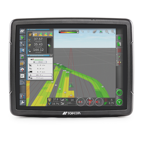
The console has a 13.5" LCD touch screen display. The back panel of the X35 console has a few Figure 1.3. connection ports, refer to 1. Ttwo CAN ports which are used for harness connections;... -
Page 14: Switchbox
Figure 1.6. This harness connects the The on-frame switchbox is installed on the frame X35 console to a power source, ISOBUS, and GPS to control the meters in calibration mode. It is signal. also used to run meters to check runs when the unit is stationary. -
Page 15: Power Extension Harness
X35 console System Components 1.4.2 Power Extension Harness Power extension harness connects X35 console to the power source. There are two power extension harnesses available: 1. with the auxiliary connector to connect in the Figure 1.7). cab (3151-69, refer to 2. -
Page 16: In-Cab Switchbox Harness
Tractor ISOBUS Harness Figure 1.9- Switchbox ISOBUS Adapter Harness (3132-42) Tractor ISOBUS harness connects to battery and tees into X35 harness. Implement plugs into harness at back of tractor. Connects to 9- pin AMP ISOBUS connection in the tractor cab... -
Page 17: Electronic Control Unit (Ecu)
X35 console System Components Electronic Control Unit (ECU) 1.5.1 Master ECU (CM-40) 1.5.2 I/O ECU (EM-24) (optional) The Master ECU (Figure 1.13) is located on the The I/O ECU (Figure 1.14) is located on the back hopper panel of the air seeder. It is capable of: side of the same mount as the Master ECU. -
Page 18: Sl2140 Scale Link Ecu
System Components X35 console 1.5.3 SL2140 Scale Link ECU Integrates the Digi-Star weigh system into the X35 Apollo system so live weights can be monitored. Setup can be accessed through the X35. Scale_Link_ECU.jpg Figure 1.15 - Scale Link ECU 1.5.4... -
Page 19: Speed Sensors
The sensor will trigger an alarm when there is no product in front of it. The X35 provides a calculated (not actual) method of reporting the product remaining in the tank. This value is based on the metering auger output in relation to the product amount entered at time of fill. -
Page 20: Bhecu (Blocked Head Electronic Control Unit)
20 BH sensors per unit. Figure 1.20 - I/O ECU (EM-24) The information from this BH sensor is then sent back to the X35 monitor and is displayed on the Bourgault SRC program. Refer to Section 13.3... -
Page 21: Overview
X35 Console Overview 2 Overview 2 Overview ............................2.1 Starting the X35 Console ......................2.2 2.1.1 Turning On ........................2.2 2.1.2 Shutting Down ......................2.2 Console Toolbar ........................2.4 Understanding Main Screens ....................2.5 2.3.1 Operations Screen .......................2.5 2.3.2 Manipulating Main Viewing Area .................2.6 Common Functions .......................2.7 Guidance/Coverage Map ......................2.9... -
Page 22: Starting The X35 Console
Refer to Section 11 - Wiring Schematics for more details. Power Ensure that the X35 is connected to a stable power Button supply; direct battery connection is best however many newer model tractors have direct to battery connections available in the cab. - Page 23 Section 4.2 - GPS. Also ensure that all harnessing is correct and properly connected. You may also verify the X35 is receiving GPS signal, refer to Section 10.1.2 - Dashboard Items & Section 10.3 - GPS Details.
-
Page 24: Console Toolbar
X35 Console Console Toolbar The Configure Home Screens button will The X35 has some dedicated buttons/controls on the lower console toolbar which is accessed by open a window to save or replace global scrolling up from the bottom edge of the screen. -
Page 25: Understanding Main Screens
The operations screen will allow you to access all When system is not ready, the icon will be the controls available on the X35 Console. The Red. Press the icon to bring up a Status functions on the screen are separated into several menu to see what is preventing seeding. -
Page 26: Manipulating Main Viewing Area
Overview X35 Console 2.3.2 Manipulating Main Viewing Area Selecting any feature on the Mini-View menu will Figure 2.9. open a mini-view window, refer to Some mini-views have a maximize arrow and will expand to display more information. 1. to view more information select the top right maximize arrow or touch the mini-view and slide towards the main screen;... -
Page 27: Common Functions
X35 Console Overview Common Functions There are several common functions that are used with the X35 console. 1. Cancel Button Cancel button will cancel the selection/ action and return to previous screen. 2. Confirm (OK) Button Confirm/Ok button will confirm the selection/action to continue. - Page 28 Overview X35 Console 5. QWERTY Keyboard Refer to Figure 2.12. When it is required to enter text, for example when entering a tank or implement name. A QWERTY keyboard will appear. You can enter text using upper and lower case letters. You can use the backspace to delete the last symbol.
-
Page 29: Guidance/Coverage Map
X35 Console Overview Guidance/Coverage Map The full Guidance screen opens as default when B Zoom Out - helps to get a wider view of your the Operations screen is accessed for the first time. implement and map on your guidance screen. - Page 30 VRC Map - will display a VRC map (if Variable Rate Control has been set up with a X35 controller and has been enabled) The VRC map for a specific tank can be selected using left and right arrows.
- Page 31 X35 Console Overview Applied Rate Map Legend - shows the range of product rate values indicated by the colour intensity or different colour scheme. Refer to Figure 2.16. Selecting the legend will bring up a window showing rates range and...
-
Page 32: Seeder Controller
Overview X35 Console Seeder Controller Refer to Figure 2.17. This is the Seeder Controller Icon, located in Mini-View menu. Selecting this icon Expand will open Seeder Controller mini-view window. The Seeder Controller mini-view window can be expanded into a main screen. -
Page 33: Seeder Controller Mini-View Window
X35 Console Overview 2.6.1 Seeder Controller Mini-View Window Figure 2.20. Refer to Mini-view Seeder Control window has several tabs at the top that display information for different air seeder features. Only enabled features and tanks will be displayed. When there are more than five features available, tab with arrow will appear to allow to move to the next page. -
Page 34: Seeder Controller Full Screen Mode
Overview X35 Console 2.6.2 Seeder Controller Full Screen Viewing area position Mode status bar Figure 2.21. Refer to The Seeder Controller menu, is located on the right side and has icons, that if selected will open up panels for the enabled granular/liquid or NH3 tanks, configuration panel, area counters panel (if... - Page 35 X35 Console Overview D Area Counters panel - for detailed Viewing are position information refer to Section 2.6.5 - Area status bar Counters Panel. E Fan Status panel toggle - this icon works like a toggle switch, making the Fan Status panel (F) visible or not.
-
Page 36: Tank Tab/Panel Explained
Overview X35 Console 2.6.3 Tank Tab/Panel Explained A Requested Application Rate - used to enter and display the application rate. The control system will use the calibration factor to adjust the metering auger speed for the given product. B Used to decrease requested application rate by preset increment. - Page 37 X35 Console Overview G Rate Control Mode selector - appears only when the Variable Rate Control is enabled in Setup/System/Features/Implement and allows you to select a VRC or Auto control for a Figure specific tank or all products. Refer to 2.25.
-
Page 38: Tank Parameters
Overview X35 Console 2.6.3.1 Tank Parameters Discharge Rate - displays the amount of Figure 2.26. Refer to product being metered per minute from the tank. Application Rate - this is the current Area Remaining - displays the area application rate for the product in the specific tank. -
Page 39: Configuration Panel
X35 Console Overview 2.6.4 Configuration Panel Refer to Figure 2.27. A Manual Speed - allows the user to enable or disable the manual speed control. When enabled, the button will have green background. Important The SET manual speed must be maintained to achieve the rates that have been set. -
Page 40: Area Counters Panel
Figure 2.28. The area counters section has a total of 10 possible areas. For each tank and each area, the X35 console will record: the treated area, ASC savings, product used, operating time, average rate and productivity rate. These accumulate whenever the master switch and the particular tank switch are on. -
Page 41: Working With Global Home Screens
X35 Console Overview Working With Global Home Screens 2.7.3 Managing Screens Operation screens can be set up in many ways. To manage the screens, press the Configure Home Once a screen is set up it can be saved as a home Screens button so the "Manage Global Home... -
Page 42: Loading (Selecting) Global Home Screen
Overview X35 Console 2.7.4 Loading (Selecting) Global Home Screen If the "Global Home Screen Mode" is set to Select, (refer to Section 3.2.3 - Environment) pressing the Go to Home Screen button will bring up the Load a Global Home Screen window, that Figure 2.31. -
Page 43: Setup
X35 Console Setup 3 Setup 3 Setup ............................3.1 Setup menu Explained ......................3.2 User ............................3.4 3.2.1 Region .........................3.4 3.2.1.1 Language ......................3.4 3.2.1.2 Time/Date ......................3.5 3.2.1.3 Units ........................3.6 3.2.2 Lightbar ........................3.6 3.2.3 Environment ........................3.7 3.2.4 Map ..........................3.8 3.2.5 Access Level .......................3.9 3.2.6 User Controls ......................3.10... -
Page 44: Setup Menu Explained
The main level has the following items: This screen is where you can setup and configure 1. User - allows you to select language, set the X35 console environment, vehicle, implement date/time, units, lightbar, console working and air seeder. You may also enable the additional... - Page 45 X35 Console Setup 5. Product options - allows you to create a product list, set product density, preset rates and calibration factors. Refer to Section 7 - Product Setup. Selecting one of the items in the main level of the menu will unfold the next level of options.
-
Page 46: User
Setup X35 Console User User settings allow the user to setup the console work environment, regional settings and map options. To access the user settings select the User icon in the main setup screen. Refer to Figure 3.4. 3.2.1 Region Region settings include language settings, time and units. -
Page 47: Time/Date
X35 Console Setup 3.2.1.2 Time/Date From the Main Setup menu select User/Region/ Time/Date. There are three settings: 1. Date format - select a format for how you would like the date to appear on the console: a. 15 Dec, 2012 (Day Month, Year) b. -
Page 48: Units
Setup X35 Console 3.2.1.3 Units 8. Dry Density Units - select Kilograms per Litre, Kilograms per Cubic Meter, Kilograms From the Main Setup menu select User/Region/ per US Bushel, Kilograms per UK Bushel, Units. There are several settings: Pounds per Gallon, Pounds per Cubic Foot, Pounds per US Bushel, Pounds per UK Bushel 1. -
Page 49: Environment
Using plus/minus buttons will change 5. System 150 File Transfers - enables or volume in increments. disables file transfers from earlier Topcon 2. Button Clicks - when Enabled there will be systems (110/150). a click with every button selection on the 6. -
Page 50: Map
Setup X35 Console 3.2.4 3. Map Focus Auto-Shift - enables or disables the map focus auto-shift. From the Main Setup menu select User/Map. The a. When enabled, the map will automatically following settings will allow the set up of how refit in the main viewing area when... -
Page 51: Access Level
X35 Console Setup 3.2.5 Access Level From the Main Setup menu select User/Access Level. This tab allows you to switch access levels. Someone with a higher level of understanding of the system can setup two lower access levels with limited access to settings/functions only allowing them into areas they need to access for operation. -
Page 52: User Controls
Setup X35 Console 3.2.6 User Controls From the Main Setup menu select User/User Controls. This tab only appears for the Expert access level and allows you to set what controls the other access levels can view/change. 1. Under each access level column, select all the Control items to make them visible for the respective access level. -
Page 53: Remote Support
X35 Console Setup 3.2.7 Remote Support Allows you to setup support desks and request support if you have the X35 console connected to an internet source. Refer to Section 4.1.6 - Wireless to setup internet connection. Will need to contact your dealer to use this option. - Page 54 Setup X35 Console 3.12...
-
Page 55: System
X35 Monitor System Settings 4 System 4 System ............................4.1 Features ..........................4.2 4.1.1 Licenses ........................4.2 4.1.2 Console ........................4.2 4.1.3 Guidance ........................4.4 4.1.4 Implement ........................4.5 4.1.5 Xtend ...........................4.8 4.1.6 Wireless ........................4.9 4.1.7 Quick Start .........................4.10 GPS .............................4.12 4.2.1 Receiver ........................4.13 4.2.2 Output ........................4.14 4.2.3... -
Page 56: Features
This page shows the features that are unlocked Note on the console. It also allows you to export the license data file which is used by Topcon to Only features that are registered for the product generate a new license data file for the specific purchased can be enabled. - Page 57 X35 Monitor System Settings 3. File Server - files for an ISOBUS ECU can be 6. Cloud Based Services - allows the user stored on the file server. This setting enables to disable or select one of the two cloud or disables the file server, if the ECU has file...
-
Page 58: Guidance
The rest of the settings on this page are related start mode will be displayed on the guidance/ to Topcon Auto Steer System. Please refer to the coverage map screen on the right side above Topcon Auto Steer Operator’s manual or contact the job/guidance menu. -
Page 59: Implement
X35 Monitor System Settings 4.1.4 Implement Available only When ASC enabled To access the implement features settings from the Main Setup menu select System/Features/ Implement, refer to Figure 4.4. 1. Auto Section Control (ASC) - enables or disables auto section control. When ASC is... - Page 60 2. Variable Rate Control - enables or disables the use of the VRC feature in conjunction with seed rate control of the X35 console. If enabled this feature will allow the use of prescription maps to vary application rates over the mapped areas.
- Page 61 X35 Monitor System Settings 6. Water Conservation - this is a locked feature available for land leveling/drainage. 7. Norac Boom Height Control - this is an option for sprayer implements for auto boom height control. 8. Lock Setup Menu When Master Switch On...
-
Page 62: Xtend
System Settings X35 Monitor 4.1.5 Xtend This page shows the devices that have been connected to console through the Xtend feature. Refer to Section 13.5 - Extend Feature operation of this feature. 1. Console Name - open this tab to change the name of the console to show up on connecting device. -
Page 63: Wireless
X35 Monitor System Settings 4.1.6 Wireless The following settings apply when this wireless hotspot is enabled. This page only shows up if the Wi-Fi antenna is 3. SSID - this is the name of the hotspot that is connected into the console. -
Page 64: Quick Start
System Settings X35 Monitor 4.1.7 Quick Start When the Job Helper mode is set to Quick Start Section 4.1.3 - Guidance), prompts for (refer to specific jobs that will be carried out, can be customized under System/Features/Quick Start. There are several options that can be enabled or disabled. - Page 65 X35 Monitor System Settings 4. Change Job - will prompt to select or create a job with a Default, Custom or Entered name. 5. Configure Job Regions - will prompt to assign internal boundaries to work or exclude. 6. Load VRC Map - will prompt to automatically load a VRC map from the inserted thumbdrive.
-
Page 66: Gps
System Settings X35 Monitor The X35 console can interact with a GPS that is used in the following applications: guidance, variable rate control and mapping. The GPS signal is also used to determine ground speed (the preferred method). To access GPS settings from the Main Setup menu select System/GPS. -
Page 67: Receiver
Type set as Other. GPS receivers need to be outputting GGA, VTG & ZDA strings for the X35 console. Refer to the manual for your GPS equipment. 2. Baud Rate - baud rate refers to the speed of the data transfer and depends on the equipment being used. -
Page 68: Output
A green check mark indicates that 1. GPS Output - enables or disables the output a sentence code enabled, a red cross means it is of the GPS data from the X35 console to other disabled. devices. -
Page 69: Radar
4.2.3 Radar The Baud rate depends on the equipment that The X35 console can provide radar output to the gps data will be transferred to. Refer to the external devices. To access Radar output settings operator’s manual for that specific device for its... -
Page 70: Serial Ports
System Settings X35 Monitor Serial Ports This setting is used to set which port on your X35 console will receive GPS signal. It will also send the signal to other devices, that are not directly connected to GPS select System/Serial Ports. -
Page 71: Alarms
X35 Monitor System Settings Alarms 1. Enabling/Disabling Alarms - all general Alarms are provided as a warning if any components or functions of the seeding system, alarms can be enabled/disabled all at once or steering, or GPS are not functioning properly. All individually. - Page 72 For the End of Row alarm to sound, auto steering must be enabled (in Topcon systems only). If there is no auto steering, the Look Ahead Distance function can be used to set a distance in front of the vehicle icon on the Figure 4.20 - End of Row Alarms...
-
Page 73: Seeder Alarms
X35 Monitor System Settings 4.4.2 Seeder Alarms To access the seeder alarms setup, select System/ Alarms/Seeder. All seeder alarms are displayed on the left side of the setup screen in a scroll down list. A green check mark next to the alarm name indicates that this alarm is enabled;... - Page 74 3. No Comms - indicates no communication between the X35 and the ECU(s) on the Figure 4.22 - Incorrect Rate Alarm seeder. 4. Tank Empty (Sensor) - there is no product in front of that tank's bin level sensor.
- Page 75 X35 Monitor System Settings 16. High Auxiliary RPM Speed - not used 27. High Fan Speed - indicates that the fan RPM is more than the HIGH RPM setpoint. 17. Low Auxiliary RPM Speed - not used a. select the Fan 1 Maximum RPM button to 18.
- Page 76 Section 12 - Troubleshooting. 40. Scale Setup Number Mismatch - Indicates if the X35 settings for the scale setup number a. Scale - change which scale you are setting doesn’t match the actual Scale Link value for a the parameters for.
-
Page 77: Flag Points
X35 Monitor System Settings Flag Points The operator can set flag points on the guidance map to show obstacles or other land features for a field on the Operations Screen. Here, the operator can view flag point presets and change the preset symbols and names as desired. -
Page 78: Isobus
System Settings X35 Monitor ISOBUS Settings in System/ISOBUS are used to configure the Universal Terminal & the Task Controller for controlling ISO programs. 4.6.1 Task Controller Setup Access TC (Task Controller) settings through System/ISOBUS/TC. Configure the TC for running ISO programs. -
Page 79: Universal Terminal Setup
X35 Monitor System Settings 4.6.2 Universal Terminal Setup 4. Clear Pool Cache - clears contents of universal terminal cache, used if error is Access UT (Universal Terminal) settings through displayed. System/ISOBUS/UT (this tab only appears if the 5. Soft Keys Per Column - can be configured UT is enabled under System/Features/Console). -
Page 80: Utilities
System Settings X35 Monitor Utilities Access certain console functions through System/ Utilities. 1. Provision USB For Upgrade - this will unlock the thumbdrive to prepare for software upgrade. Note Ensure that the upgrade files are present on the thumbdrive (unzipped) and at the root (not in a folder). -
Page 81: Vehicle
This section explains how to set up and access the profile information about the vehicle on which the X35 console is mounted. If the console is to be used on more than one vehicle, then more than one vehicle profile will need to be set. -
Page 82: Selecting An Existing Vehicle
USB is not connected, connect a USB device 3. The "+ New vehicle as Copy" window will appear. Select the vehicle name button to give to the X35 console, it will also enable the USB a new name and confirm. button. -
Page 83: Setting Up A New Vehicle
X35 Console Vehicle Setup Setting Up a New Vehicle To setup a new vehicle select Vehicle/New. Refer to Figure 5.2. A list with vehicle manufacturers will appear. Use the up/down arrows or scroll bar to see all the options. If you find the make for your vehicle, or can... - Page 84 Vehicle Setup X35 Console b. Next, a model list for the chosen vehicle will appear. Use the up/down arrows or the scroll bar to see all the options. Choose your model and confirm. Figure 5.3 - Vehicle Model Selection c. A "+ New Vehicle" window will appear.
- Page 85 X35 Console Vehicle Setup 2. If your vehicle make is not present, or can not be closely matched; a. Choose "Other" as your vehicle make and confirm. Figure 5.5- Vehicle Make Selection - Other b. Next, a list with auto steering systems will appear.
- Page 86 Vehicle Setup X35 Console c. Next, a range of generic vehicle templates will be displayed. You can select from: tracked, articulated, front steerable, harvester, sprayer, or swather. Front Steerable Swather Articulated Harvester Sprayer Tracked Use these arrows to display more options Figure 5.7 - New Vehicle Type...
-
Page 87: Setting Up Vehicle Geometry
X35 Console Vehicle Setup Setting Up Vehicle Geometry Note Dimensions will vary depending on the type of Pre-defined factory vehicle templates contain vehicle selected. standard measurements. Measurements can be adjusted to correct for the particular vehicle, tire Following is a list of commonly used size and other factors. -
Page 88: Steering
Configure steering settings if it is being controlled The number is positive when the receiver is through the X35 monitor (settings only appear if in front of the rear axle and negative if it is a Topcon GPS receiver is selected under System/ behind the rear axle. -
Page 89: Implement Setup
X35 Monitor Air Seeder Setup 6 Implement Setup 6 Implement Setup ..........................6.1 Selecting an Existing Implement ...................6.3 Creating a New Implement Profile ..................6.5 6.2.1 Creating a New Profile Based on Factory Templates ..........6.5 6.2.2 Create a Custom Implement Profile ................6.11 ECU .............................6.22... - Page 90 Air Seeder Setup X35 Monitor 6.6.3 Fan Settings ......................6.53 6.6.4 Pumps Settings ......................6.54 6.6.5 Drill Control ........................6.55 6.6.5.1 Lift Master Settings .....................6.55 6.6.5.2 Pack Master Settings ..................6.56 6.6.5.3 Control Settings ....................6.57 6.6.6 Accessories .......................6.58 6.6.6.1 Sensor Setup ......................6.58 6.6.6.2 Blocked Head Monitor ..................6.59 6.6.6.3...
-
Page 91: Selecting An Existing Implement
"implements" which then allow the and seeding drill) have been already setup on the user to move the X35 console between machines X35 console or will be imported from a USB to maximize its value. device. In seeding applications: 1. - Page 92 Air Seeder Setup X35 Monitor 3. Copying an existing profile: You can copy one of the existing profiles and make the required changes. To do that: a. Select the implement you would like to copy (it will have white background).
-
Page 93: Creating A New Implement Profile
X35 Monitor Air Seeder Setup Creating a New Implement 6.2.1 Creating a New Profile Based on Factory Templates Profile There are 2 options for creating a new implement To create new implement profile based on the profile. Select one of the options explained below. - Page 94 Air Seeder Setup X35 Monitor 3. Select a specific tank configuration from the g. 6450 3 TANK-MTRG-T3 1 FAN - is a list. A naming convention is used to help Model 6450 with 3 tank metering with an easily identify the required configuration.
- Page 95 X35 Monitor Air Seeder Setup 4. Select the appropriate ECU Type which is Apollo for new machines. 5. Select a Template for a Drill a. Bourgault - select this for Bourgault units. If your drill isn’t on the list or you have...
- Page 96 Air Seeder Setup X35 Monitor Select Configuration Folder Select Drill Model Select Drill Size Select Drill Configuration Figure 6.6 - Selecting Drill...
- Page 97 X35 Monitor Air Seeder Setup Select your drill configuration. a. A naming convention is used to help easily identify required configuration. b. Following examples explain the naming convention: 3320-76 10SPCG - is a Model 3320, 76' width, 10" spacing 3320-76 12SPCG HF - is a Model 3320, 76 width, 12" spacing, High flotation frame iii.
- Page 98 After the implement name is entered and confirmed, the X35 console will restart and come back to ECU Setup page, refer to Figure 6.8. Important The next step will be to get the X35 to recognize Figure 6.8 - ECU Setup 6.10...
-
Page 99: Create A Custom Implement Profile
X35 Monitor Air Seeder Setup 6.2.2 Create a Custom Implement d. A window will appear informing you that the system will restart once your air seeder Profile has been configured, refer to Figure 6.9. To create a new custom implement profile, select e. - Page 100 Figure 6.11 - Air Seeder Name b. Type the desired name and select OK to accept it. 3. For Implement control; c. The X35 console will advance to the next Select the type of control, that the X35 console step. will be responsible for.
- Page 101 Figure 6.13. b. Select the "ECU Type" button to open a drop down list. c. Select Apollo for a new Bourgault air seeder with the X35 console. ECU Type Button Figure 6.13 - ECU Type 5. For Implement Function; a. Refer to Figure 6.14.
- Page 102 (if these options installed) must be disconnected. Important Refer to the following table, when connecting ECUs to make sure that the right ECU is connected when prompted by the X35 console. Identification of ECU connections by X35 console Tanks #1-4 Apollo CM-40 1 These ECU’s are part of a...
- Page 103 Air Seeder Setup Figure 6.17. b. Press the right arrow and the X35 will try to detect the main ECU. Refer to Figure 6.17 - Detecting ECU #1 c. Once detected, the X35 will confirm that in the new window. Refer to Figure 6.18...
- Page 104 If there are additional ECUs present for this system, select the add ECU button on the Apollo system configuration summary window. The X35 will prompt you to connect the next ECU, refer to Figure 6.20. Connect ECU connector and select Next.
- Page 105 X35 Monitor Air Seeder Setup 7. For Selecting Seeder Manufacturer; a. From the pop-up menu select the seeder manufacturer. Refer to Figure 6.22. b. Select Bourgault. Figure 6.22 - Selecting Seeder Manufacturer 8. For Selecting number of Booms; c. Set the Number of multi-section Liquid/ NH3 booms: a.
- Page 106 Air Seeder Setup X35 Monitor 9. Number of Fans - enter the number of fans installed on your air seeder tank. a. If "1" is entered, the fan setup screen will have settings only for one fan (refer to Section 6.6.3 - Fan Settings).
- Page 107 X35 Monitor Air Seeder Setup 11. Tanks - here you can enter the number of tanks on your air seeder and whether it has a Flex tank or not. Note Tanks without metering augers still count as a tank (other than a Flex tank).
- Page 108 Air Seeder Setup X35 Monitor 12. Tank Summary - shows a list of tanks, the product type for each tank and the assigned ECU channel will be displayed. Here you can perform following functions: a. Rename tank(s); b. Change the product type for the tank from...
- Page 109 (refer to Section 6.6.1.1.2 - Individual Tank Setup). Figure 6.28 - Tank Summary - Example 13. The custom profile setup is complete. Confirm to apply settings and restart the X35 console. Figure 6.29 - Custom Implement Profile Complete 6.21...
-
Page 110: Ecu
Air Seeder Setup X35 Monitor 6.3.1 ECU Setup After creating a new implement profile or changing implements, the new implement will be loaded and the ECU Display window will be displayed. This window displays a summary of all tanks, the type of each tank... - Page 111 X35 Monitor Air Seeder Setup 3. Add Tank - this will allow you to add a tank in situations when the Saddle tank or liquid/NH3 system is added to the existing tank. a. When selected, a message, that this operation requires restart will be displayed.
-
Page 112: Ecu Manage
Air Seeder Setup X35 Monitor 6.3.2 ECU Manage Important When creating a new factory profile all of the This section is used to detect, add or replace an ECU's need to be detected individually. ECU. Select the Implement/ECU/Manage button. Refer to Figure 6.33. - Page 113 Once the ECU is connected, select NEXT. Figure 6.35 - Connect ECU 3. The X35 console will attempt to detect an ECU. 4. Once an ECU is detected, a confirmation message will be displayed. Select NEXT to continue.
- Page 114 Air Seeder Setup X35 Monitor 5. The Apollo system configuration summary will 8. The Replace option can be used to re-detect an be displayed. Select "yes" to apply settings. ECU on the list with a new replacement ECU. Refer to Figure 6.36.
-
Page 115: Add New Ecus
X35 Monitor Air Seeder Setup 6.3.3 Add New ECUS 5. When done select the "yes" button (green check mark) to finish and return to the Add/ To add a new ECU, select Implement/ECU/Manage Replace ECU main screen. and then select the Add New ECUs button, refer to 6. -
Page 116: Geometry
If a Factory profile is selected most This setting is designed for Topcon Auto Steer of the dimensions will be preset but each boom Control and will let you select what boom should tab should be reviewed to enter the appropriate be used for guidance. - Page 117 X35 Monitor Air Seeder Setup Figure 6.41 & 6.42. B. Overlap - indicates the width of the overlap Refer to between two adjacent swathes. It is mostly A. Swath Width - sets the working width of the used for auto steer and guidance.
- Page 118 Air Seeder Setup X35 Monitor D. Implement Wheels Offset - defines the F. Trailer Wheels Offset (used for Leading Air distance from pivot point of the drill to front Seeders ONLY) - is the distance from the row of openers. Enter: airseeder tires to rear hitch pin.
-
Page 119: Section Control
X35 Monitor Air Seeder Setup Section Control Note Boom is a term derived from Sprayers and more Note generally applies to a product being applied. In The Section Control Icon only appears if the seeding scenarios, your machine will have one implement was setup with Section Control full-width granular product "boom"... - Page 120 Air Seeder Setup X35 Monitor Important 3. The width and number of nozzles for each section can be entered individually by selecting The total width should match for all booms unless the Width button and the Nozzles button for you have a unique implement setup.
- Page 121 X35 Monitor Air Seeder Setup b. Select the Width button for "All". c. Select the Nozzles button for "All". A keypad will appear and will have A keypad will appear. an additional button, that shows the Enter the value and confirm by currently used units.
-
Page 122: Timing
Air Seeder Setup X35 Monitor 6.5.2 Timing This will set the times for product to get from the section control valves to the openers. Important 1. The first tab will allow you to set if each boom will have custom settings or you can Accurate times are critical to the proper function copy settings from a specified boom. - Page 123 X35 Monitor Air Seeder Setup 2. Select a boom from the tabs on the left side, The On/Off time can be set for several or all of the name of that boom will be shown in the the sections at once (ex. Pick 2 inner sections and title bar.
-
Page 124: Section Switch
Air Seeder Setup X35 Monitor 6.5.3 Section Switch In this section, you can enable and configure a virtual section switchbox, that allows manual override control of the sections for each boom. If left disabled the sections will always stay on, unless the ASC shuts them off corresponding to the coverage map. -
Page 125: Seeder
X35 Monitor Air Seeder Setup Seeder 6.6.1 Granular Setup a. Check the time from the rear tank (for TBHD) and the front tank (for LDG) to 6.6.1.1 Granular Tank Setup get the longest time (worst case). 4. OFF time To Ground (Full width To access the tank setup select Implement/Seeder/ configuration) - is a time from when the... - Page 126 Air Seeder Setup X35 Monitor 6. Preload time - this setting is only effective for 7. Fan Speed to Start - enter the minimum fan 7000 AS with a hydraulic drive. This is the speed at which the meters may be activated.
-
Page 127: Individual Tank Setup
X35 Monitor Air Seeder Setup 6.6.1.1.2 Individual Tank Setup 4. Section Control (7000AS) - these settings appear only if granular section control is To access the individual tank setup select the enabled in the profile. numbered tab that corresponds to the tank that you... - Page 128 Air Seeder Setup X35 Monitor Sectional Boom: 5. On Time to SC location - should be the time from when meter starts until product is at the section valve. 6. Off Time to SC location - should be the time from when meter stops turning until product stop flowing through section valve.
-
Page 129: Tank Grouping
X35 Monitor Air Seeder Setup Important 6.6.1.2 Tank Grouping Remember that selecting a tank grouping only Depending on how the implement profile was sets the monitor up that way and the interconnect created, using the Bourgault factory profiles or if it... - Page 130 Air Seeder Setup X35 Monitor Figure 6.59. Refer to 4. Select the tank that you would like to add to Important another tank (combine them using interconnect Only tanks that have interconnect covers covers). between them can be combined. Do not create a.
-
Page 131: Drive Setup
X35 Monitor Air Seeder Setup 6.6.1.3 Drive Setup a. Drive Type - select the drive type that is used on your air seeder: Here you will be able to configure settings related 7000 Series - Proportional Valve to the metering drive for each tank that has a (an electric PWM valve on each metering auger installed. - Page 132 Air Seeder Setup X35 Monitor Important c. Minimum shaft RPM (7000 Series ONLY) - should be set at 10 rpm. These are the stamp identifiers found on the auger shaft. d. Maximum shaft RPM (7000 Series ONLY) - should be set at 1000 rpm.
-
Page 133: Control Setup
X35 Monitor Air Seeder Setup 6.6.1.4 Control Setup Minimum / Maximum PWM are the limits of the PWM drive and are represented in the percentage Note of voltage drive to the coil. These settings are for 7000 Series air seeders 1. -
Page 134: Nh3/Liquid Setup
NH3/Liquid Setup 6.6.2.1.2 Individual Tank Setup Specific settings for an NH3/Liquid tank located in The X35 console has the capability to control and the tank number tab under Implement/Seeder/NH3/ monitor the air seeder tanks and an NH3 applicator Tank. Refer to Figure 6.66. - Page 135 X35 Monitor Air Seeder Setup This time can be left at 0 and the section control 4. Section Control - available selections are Full timing can be set to account for the sequence Width and NH3/or Liquid. timing. a. If using sectional control, select NH3...
-
Page 136: Flow Settings
flow bypasses back to the tank when the getting the final value to be entered into the X35 section valves close. monitor. Check with the installer of your NH3 system to confirm the calibration factor and units... -
Page 137: Control Valve Settings
X35 Monitor Air Seeder Setup 6.6.2.3 Control Valve Settings b. Regulator Valve - this valve uses a motor to open or close the valve depending on 1. Controller Type - these settings refer to the the flow requirements. operating characteristics of control valves Positive or negative power is applied for NH3 or liquid systems. -
Page 138: Proportional Valve Settings
Air Seeder Setup X35 Monitor 6.6.2.3.1 Proportional Valve Settings 3. Controller Response - this will adjust how fast the controller will respond to changes. 1. Flow Meter Sampling - the default setting The default is set to Fastest. is "standard". The optional "Reduced"... -
Page 139: Regulator Valve Settings
X35 Monitor Air Seeder Setup 6.6.2.3.2 Regulator Valve Settings 5. Controller Mode - this is the controller model selection. 1. Flow Meter Sampling - the default setting is "standard". a. For liquid systems, most use the "Standard" model that is a 12V Spraying a. -
Page 140: Pressure Settings
Air Seeder Setup X35 Monitor 6.6.2.4 Pressure Settings 9. PWM Setting - is the Pulse Width Modulation. Pressure sensor is selected if there is an electric a. Lowering this number reduces the voltage pressure sensor in the product line (not supported supplied to the valve, slowing it down. -
Page 141: Fan Settings
X35 Monitor Air Seeder Setup 6.6.3 Fan Settings 1. Fan Speed - enables or disables monitoring of the fan speed. This section allows changes to settings related to a. If you are not using one of the fans, the fan(s). -
Page 142: Pumps Settings
Air Seeder Setup X35 Monitor 6.6.4 Pumps Settings These settings appear only if configured with NH3/ Liquid. You can configure settings related to the liquid/NH3 system pumps. Systems can have up to 4 pumps. There is a tab for each pump. -
Page 143: Drill Control
This feature is used to control the lift/lower of If Drill Control is enabled do not use implement the drill through the X35. It also creates a drill switch as the master or as secondary master. control boom that can be controlled by ASC to... -
Page 144: Pack Master Settings
6. Control Type - set to the parameter to control extra ECU on the drill to monitor the pressure and gives the ability to adjust it through the X35. the Pack Master value to. Also, it uses a load cell on one of the opener a. -
Page 145: Control Settings
X35 Monitor Air Seeder Setup Note 2. Minimum PWM - set to a minimum value that the proportional valve will be able to drive These next four settings are generated from at. Set to 5%. calibrating the pack force sensor in the Seeder Controller screen. -
Page 146: Accessories
Air Seeder Setup X35 Monitor 6.6.6 Accessories a. If the EM-24 ECU is used for section The accessories menu will allow you to set up control the sensors need be set to Granular features such as sensors, blockage monitoring Section Sense. -
Page 147: Blocked Head Monitor
6.79. Refer to be available for monitoring in the Seeder Controller mini-view window and in the This section configures settings related to the Section 13.3 - X35 expanded view, refer to Blockage Monitor. Blockage Monitoring. 1. Blocked Head Monitor - select Enabled if blockage system installed, and Disabled if there is no blockage system installed. - Page 148 2. Blocked Head Sensor Type - select one: 3. Enabled Head System - enables monitoring for one of the following: a. Dickey-John - all Bourgault X35 systems use this style of sensors. a. Seed & Fertilizer b. Standard - set for Topcon sensor.
- Page 149 X35 Monitor Air Seeder Setup 4. Number of Distribution Heads - enter the For example: SEED1 LOW (seed 1 number of secondary manifolds on the tillage left outer wing), SEED5 RMF (seed unit. 5 right main frame), FERT6 IRIW (fertilizer 6 inside right inner wing).
- Page 150 Air Seeder Setup X35 Monitor c. Assign each sensor to the appropriate Head e. When setting up corresponding heads and to show up correctly represented on the sections, refer to Figure 6.82. This shows monitor. how the blockage sensors are wired from the factory and should be assigned to show d.
- Page 151 X35 Monitor Air Seeder Setup 6 PORT PRIMARY Factory Profile Custom Profile Default Sensor Head Sec�on Sensor Head Sec�on Sensor 1 SEED1 SEED: 1 Sensor 41 Head 1 SEED: 1 Sensor 2 SEED2 SEED: 2 Sensor 42 Head 2 SEED: 2...
- Page 152 Air Seeder Setup X35 Monitor 10 PORT PRIMARY Factory Profile Custom Profile Default Sensor Head Sec�on Sensor Head Sec�on Sensor 1 SEED1 SEED: 1 Sensor 41 Head 1 SEED: 1 Sensor 2 SEED2 SEED: 2 Sensor 42 Head 2 SEED: 2...
-
Page 153: Granular Sections
X35 Monitor Air Seeder Setup 6.6.6.3 Granular Sections 6.6.6.4 General Inputs This tab appears if configured with granular ASC. This is an option that is related to other types of equipment and not used with Bourgault Air 1. To access the granular section monitoring, Seeders. -
Page 154: General Output
Air Seeder Setup X35 Monitor 6.6.6.6 General Output 4. Treadlite Drive - this option is controlled by the same drive as the QDA so it will only This setting allows you to assign a relay output show up here if the drive hasn’t already been from one of the ECU drives. -
Page 155: Weigh Scales
X35 Monitor Air Seeder Setup 6.6.7 Weigh Scales 6.6.7.1 ECU This allows the optional weigh system to be integrated into the console to monitor actual 1. The scale link ECU needs to be detected. weights. This feature needs to be enabled under Press on the Detect New ECU’s button to... -
Page 156: Scales
Air Seeder Setup X35 Monitor Important 6.6.7.2 Scales The setup numbers should not be changed from This tab allows you to configure the specific scale the factory settings. channels. Scale A is configured as the total weight of the tank. Scale B is the saddle tank if installed. -
Page 157: Assignment
X35 Monitor Air Seeder Setup 6.6.7.3 Assignment The chart lists all the tanks and the scale channels they are assigned to. 1. Under the Scale column set the scale channel for each tank. a. Set the tanks that are part of the unibody (tanks 1-4) to Scale 1-A. -
Page 158: Pressure Compensation
Air Seeder Setup X35 Monitor 6.6.7.4 Pressure Compensation d. Maximum Voltage - maximum voltage value for the pressure sensor used. Set to There is a pressure sensor installed in the tanks with dedicated load cells to measure the pressure e. Weigh Scale Pressure Compensation Value in the tank and correct for the weight that is taken off of the scales due to pressurizing the tank. -
Page 159: Speed Source
X35 Monitor Air Seeder Setup 6.6.8 Speed Source 1. Speed Source - allows user to select the speed source: a. GPS - select to use GPS signal for speed. b. Wheel Sensor - select to use the wheel sensor on the air seeder tank for speed. - Page 160 Air Seeder Setup X35 Monitor 2. Fall Back Type - this button is enabled only when Speed Source is set to GPS. In case the GPS signal is lost, to continue seeding, system will automatically switch to use speed source set in the Fallback Type. The...
-
Page 161: Audio
X35 Monitor Air Seeder Setup 6.6.9 Audio Audio can be enabled for certain operations on the monitor to indicate the function, 1. Master Switch Audio - set to enabled for an audio click when the master switch is turned on or off. -
Page 162: Speed & Position
Air Seeder Setup X35 Monitor Speed & Position Sends vehicle speed and position information to the ISOBUS for performing rate control or other functions. Defaults settings are disabled, not used. 1. ISO Ground Speed - enabled or disabled 2. GPS NMEA2000 Speed - enabled or disabled 3. -
Page 163: Operator Inputs
External Console Input - allows use of if you want to control the master switch the remote mapping connector on the X35 from the X35 console as well as the in-cab harness as an alternative master signal. switchbox. 2.. Implement Master Switch - allows use of c. -
Page 164: Keypad
Air Seeder Setup X35 Monitor 6.8.2 Keypad 2. Identify Keypad - When selected, led lights on the switchbox will flash green, yellow, red. This menu option will allow you to identify and Refer to Figure 6.97. Select this button again assign the correct in-cab and on-frame switchbox, to stop flashing. - Page 165 X35 Monitor Air Seeder Setup Note d. Increase Pack Master Value - will increase the Pack Master value by the Track Master - if turned on then the drill position preset. will follow master switch state. If master is on, drill will be lowered unless drill is manually lifted.
- Page 166 6. Tank Keys - allows you to select tank controls: the Tank Rate Change Mode, will become available, refer to Steps 7 & 8 & Figure a. Virtual - means the X35 console only will 6.99. be used to control the tank switches. Pack Master Control - engages &...
-
Page 167: On Frame (Calibration) Switchbox
If the button is held they will continue the unit is stationary. The X35 running. needs to be on the seeder controller screen for this to work. (tap button 6.6.2.2.1... - Page 168 Air Seeder Setup X35 Monitor 6.80...
-
Page 169: Product Setup
X35 Console Product Setup 7 Product Setup 7 Product Setup ..........................7.1 Adding New Product ......................7.3 7.1.1 Adding a New Product Using a Manufacturer Template ..........7.5 7.1.2 Adding a Custom Product Without a Template ............7.7 Modifying Product ........................7.9 Product Density ........................7.10... -
Page 170: Product Setup
Mixtures are only used for sprayer applications). in a tank are changed, the X35 console will ask to determine what rate settings (from the product The NH3 list has only one product (NH3) and list or from the tank) to use for the affected tanks. -
Page 171: Adding New Product
X35 Console Product Setup Adding New Product If products were previously added to the custom product list, they will be displayed under the “New From the main setup menu, select Product/Granular Product...” button and the settings buttons with the or Liquid (depending on the type of product being current values shown will be on the right side. - Page 172 Product Setup X35 Console To see the calibration factor, first select a product The X35 console will save and display calibration from the list on the left (selected product will factors for each implement and tank that product have white background). Next, select the "Show has been calibrated in, along with the flighting that...
-
Page 173: Adding A New Product Using A Manufacturer Template
X35 Console Product Setup 7.1.1 Adding a New Product Using a Figure 7.6. The next screen will 3. Refer to prompt you to select a product template. Manufacturer Template a. Using the arrows or scroll bar find the 1. Select the "New Product ..." button. A new product you would like to add and select Product Setup Screen will appear. - Page 174 Product Setup X35 Console Figure 7.7. If desired, you can 4. Refer to 5. The product setup is complete and the next change the product name. screen will prompt you to save product settings or cancel it, refer to Figure 7.8.
-
Page 175: Adding A Custom Product Without A Template
X35 Console Product Setup 7.1.2 Adding a Custom Product 4. If you are adding granular product, the next screen will prompt you to enter a product Without a Template density this is not required for a liquid product. 1. Select the "New Product ..." button. A new a. - Page 176 Product Setup X35 Console Figure 7.10. Enter product rate 5. Refer to increment, product rate preset 1 & 2. a. Rate Increment - is used during operation to increase/decrease the requested rate by a preset value. b. Product Rate Preset 1 & 2 - are preset...
-
Page 177: Modifying Product
X35 Console Product Setup Modifying Product To adjust the product presets like density, rate increment and rate presets, select Product/Granular or Liquid from the main setup menu (this selection depends on the type of product you are using). Refer to Figure 7.14. -
Page 178: Product Density
Product Setup X35 Console Product Density You can either measure product density, or refer to the product density chart in Appendix C of your air seeder tank operator's manual. To determine the density of the applied product fill the calibration pail full, level, and weigh (make sure to subtract pail weight or tare scale before weighing). -
Page 179: General Operations
X35 Console General Operations 8 General Operations 8 General Operations ........................8.1 Selecting the Product ......................8.2 Filling the Tank ........................8.5 Determine Product Allocation ....................8.8 Calibration - Granular Air Seeder Tank ................8.12 8.4.1 Manual Entry of Calibration Factors ................8.13 8.4.2 Stationary Calibration ....................8.14 8.4.2.1... -
Page 180: Selecting The Product
General Operations X35 Console Selecting the Product 1. In the Seeder Controller window (full screen mode), show the Tank that you would like to select the product for. Expand the panel for that tank. Refer to Figure 8.2. 2. Select the Product;... - Page 181 X35 Console General Operations b. To assign a product for the tank select the Product Name button (Item B, Figure 8.3) open product scroll list. Select the desired product, if it is not on the list select "new", refer to Figure 8.4.
- Page 182 General Operations X35 Console Important The product density is used for the calculation of the theoretical tank capacity. It is very important to have the correct product density entered. For instructions to determine correct product density refer to Section 7.3 - Product Density.
-
Page 183: Filling The Tank
X35 Console General Operations Filling the Tank When the air seeder, NH3 or Liquid tanks are filled or refilled, the tank levels will not automatically reset to full. Once filling is complete: 1. In the Seeder Controller window (full screen mode);... - Page 184 General Operations X35 Console 5. Tank Fill Wizard (Item H, Figure 8.6) 3. Fill the tank using the functions of the tank fill panel, refer to Figure 8.6: With the integrated weigh system the Tank Fill a. Known Weight (Item B, Figure 8.6)
- Page 185 X35 Console General Operations Important Step 3: Confirmation The Added Weight can be manually The auger should be positioned on the ground entered if adjustment is needed for while tanks are activated in the Tank Fill wizard so any of the tanks.
-
Page 186: Determine Product Allocation
General Operations X35 Console Determine Product Allocation The X35 console provides a "Tank Optimizer" tool to determine the product allocation to minimize filling requirements in the field. If there are tanks that you will not be putting product in, you can first disable them in the settings under Implement/Seeder/Granular/Tanks. - Page 187 X35 Console General Operations 2. Select the button to start adding products to the table, a line for the first product will appear in the table, refer to Figure 8.10. Remove Entry Clear all products from the table Next Step Figure 8.10 - Adding Product Details...
- Page 188 General Operations X35 Console Figure 8.13. Assign tanks for this 5. Refer to product. a. If you know the tank you will be putting this product in, select that tank from the scroll list. b. If Any Single Meter is selected, the optimizer will assign this product to one single tank.
- Page 189 9. Once you find a configuration that will fit your needs, select the green check mark to accept it. The X35 console will ask if you would like to apply this configuration, refer to Figure 8.15.
-
Page 190: Calibration - Granular Air Seeder Tank
Seeder Tank Bourgault has done a lot of work to provide factory calibration numbers for the majority of The X35 console allows the operator to manually enter calibration factors for each tank if known, or common products with the optimum metering... -
Page 191: Manual Entry Of Calibration Factors
X35 Console General Operations 8.4.1 Manual Entry of Calibration Factors On the configuration Panel select the Multi-Tank Calibration button (refer to Figure 8.16) to bring up the Calibration Method window, refer to Figure 8.17. 1. Select the Manual Entry button. The... -
Page 192: Stationary Calibration
General Operations X35 Console 8.4.2 Stationary Calibration Important It is strongly recommended to recalibrate products Important every 500 acres or every time the product is changed. This will ensure you are using the most Stationary calibration mode automatically uses accurate calibration factor. -
Page 193: 7000 Series Air Seeders
X35 Console General Operations 8.4.2.1 7000 Series Air Seeders 1. On the Calibration Method window, refer Figure 8.21., select Automatic Calibration. a. The Granular calibration wizard will start Figure 8.22. up, refer to b. Select the yellow arrow to proceed to the next step. - Page 194 Hold the PRIME/RESET button until the green lights flashes. This will reset the pulses, accumulated auger shafts revolutions and expected weight to "0" in the X35 console, preparing for actual calibration. prime/reset Figure 8.25 - Switchbox - Buttons Important It is very important to get a complete reset of...
- Page 195 During the calibration, the auger shaft revolutions and expected weight will be accumulated on the X35 console for each meter, refer to Figure 8.26 - Performing Calibration 8.26 Figure Important Collect a minimum 20lb sample for each metering auger being calibrated.
- Page 196 General Operations X35 Console 8. When calibrating for the first time it is acceptable that the calibration factor(s) might be out +/- 20%. This will depend on the product density and other variations. You should save the calibration factors and...
-
Page 197: 6000 Series Air Seeders
X35 Console General Operations 8.4.2.2 6000 Series Air Seeders 1. On the Calibration Method window, refer Figure 8.30. a. Select Automatic Calibration. b. The granular calibration wizard will start. Refer to Figure 8.31. 2. On this screen there are two options that can be changed: a. - Page 198 General Operations X35 Console 3. Engage the hydraulic power to Fan 1 circuit. Refer to your Air Seeder manual, for detailed information on calibration. 4. Prime the metering augers (fill each metering auger with product). a. Go to the Air Seeder.
- Page 199 During the calibration, the auger shaft revolutions and expected Figure 8.35 - Calibrating weight will be accumulated on the X35 console for each meter, refer to Figure 8.35. Important Collect a minimum 20lb sample for each metering auger being calibrated. The larger the sample the more accurate the calibration.
- Page 200 General Operations X35 Console 7. Turn the calibration valve OFF. 8. Weigh each sample and return to the cab to Use buttons in this column enter weights. to save calibration factors for an individual tank a. Touch the right yellow arrow to move to the next screen.
-
Page 201: Area Test
X35 Console General Operations 8.4.3 Area Test If the accuracy of the calibration factors, this function can be used to verify the correct metering rate for each tank. 1. Select Area Test to start the wizard that will guide you through the test. -
Page 202: Calibration - Nh3 Tank
NOT in the units of PULSES PER LB. OF N. A conversion factor may need to be applied before getting the final value to be entered into the X35 console. Check with the installer of your NH3 system to confirm the calibration factor and units for your system. -
Page 203: Calibration - Liquid Tank
X35 Console General Operations Calibration - Liquid Tank If the X35 system is being used to monitor and control a Liquid fertilizer applicator as part of the complete seeding system, the following procedure applies. 1. From the menu in the Seeder Controller window (full screen mode) select the Configuration icon. - Page 204 General Operations X35 Console Important b. If using a different flow meter, find the calibration factor on the flow meter body. It is recommended to perform a flow calibration Ensure that the calibration factor to ensure accurate application rates as there are units match the selected volumetric many factors that can affect the accuracy.
-
Page 205: Flow Calibration
X35 Console General Operations 8.6.1 Flow Calibration a. To see the application rate value, it is recommended to have Seeder Controller 1. To prepare, disconnect the outlet hose that is mini-view open on liquid tank tab, as connected to the distribution system on the application rate is not displayed on the tillage unit and place the end in a container. -
Page 206: Wheel Sensor Calibration
Select the Wheel Sensor button to bring up Alternatively, the wheel factor can just be adjusted the Auto Speed Cal wizard window (button until the wheel speed in the X35 matches the appears ONLY when Speed Source or speed of a trusted source. For instance, GPS speed, Fallback Type is set to Wheel Sensor, refer tractor wheel speed, tractor radar speed, etc. - Page 207 X35 Console General Operations 2. Follow the instructions. 3. Move the vehicle to align a wheel magnet with the sensor. Refer to Figure 8.53. 4. Mark the ground alongside one of the tractor or seeder wheels. 5. Return to the cab, on the calibration wizard screen select yellow arrow to proceed to the next step.
- Page 208 General Operations X35 Console Important These are theoretical values and should be verified for accuracy as variations in tire size, inflation pressure, etc will cause differences. 7000 Series Air Seeder Model Tire Type Theoretical Wheel Factor 900/60 R32 (Single) 0.235...
-
Page 209: Fan Settings
1. Once the fan speed is determined, engage the hydraulics to start the fan. 2. Adjust the hydraulics to obtain the desired fan speed referencing the display on the X35 console. Important Figure 8.58 - High Fan Speed Alarm... -
Page 210: Checking Distribution Runs And Asc Valves
313226_SwitchBox.jpg 1. Ensure the Air Seeder fan(s) are running. Figure 8.60 - On Frame Tank SwitchBox 2. Units with ASC: Ensure the section switches are ON on the X35 console, refer to Figure 8.61. Figure 3. At the on-frame switchbox (refer to 8.60), turn on the tank buttons for those meters... -
Page 211: 6000 Series Air Seeder
X35 Console General Operations 8.9.2 6000 Series Air Seeder 7. If there is no product at an opener, it may be possible that the secondary manifold and/ With the seeding implement in the field position, or hose supplying product to that opener is but with the seed boots out of the ground: plugged. -
Page 212: Using Auto Section Control
field: seeded/unseeded area, within or outside of the field boundary/headlands. ASC works with the guidance system, that is a standard feature on the X35 console and always enabled. To access ASC select the icon from the... - Page 213 X35 Console General Operations b. Set the Control Mode for each boom. Refer to Figure 8.64. Drag the slider from 0 to 100. Or select the button and enter a value from 0-100. 100 - would ensure that all areas of the field will be seeded.
- Page 214 General Operations X35 Console 2. Boundary Limit - this will set the boundary This button acts like a toggle switch for area that will be seeded. There are four and will allow the user to turn ON or choices: OFF the Auto Section control. With ASC turned OFF, all products will be applied as a.
-
Page 215: Virtual Section Switches
X35 Console General Operations 8.11 Virtual Section Switches For Virtual Section Switches setup refer to Section 6.5.3 - Sections Switch. When the virtual section switches are enabled they can be accessed for each multi-section boom from the operator's screen in several ways: Figure 1. - Page 216 General Operations X35 Console 3. On the section state panel in the Seeder Controller window (expanded mode). a. Refer to Figure 8.69. b. When two or more granular and/or NH3/ Liquid booms are configured there will be a bar shown for each boom.
-
Page 217: Starting A New Field/Job
X35 Console Field / Job 9 Starting a New Field/Job 9 Starting a New Field/Job ......................9.1 Introduction ..........................9.2 Field Menu ..........................9.4 9.2.1 Selecting an Existing Field ..................9.4 9.2.2 Starting a New Field ....................9.5 9.2.3 Unload Field ........................9.5 9.2.4 Setting Flag Points ......................9.6 9.2.4.1... -
Page 218: Introduction
Menu. a. Go to Setup. Important b. From the menu, select System/Features/ With a GPS signal detected ,the X35 console will Guidance not allow product application without first loading a job (master switch will remain red). c. For Job Helper Mode, select Job Assist or Quick Start. - Page 219 9.3. & Quick Start Icon Job Assist Icon Figure 9.2 - Job Assist Figure 9.3 - Quick Start 4. The X35 console records and stores Client information about the client, farm, field and the jobs as shown in Figure 9.4.
-
Page 220: Field Menu
The field menu provides the tools to set client, farm, boundaries, flag points and exclusion zones. The X35 console will store information such as boundaries, obstacles, exclusion zones, guidelines under the field, so it is can be easily recalled for other jobs in the same field. -
Page 221: Starting A New Field
X35 Console Field / Job 9.2.2 Starting a New Field Refer to Figure 9.5. 1. From the Job/Guidance Toolbar on the right side of the guidance screen select the Field icon and then select to open up Figure the Add New Field window, refer to 9.7. -
Page 222: Setting Flag Points
Field / Job X35 Console 9.2.4 Setting Flag Points Flag points are used on the guidance map to indicate obstacles and noted items in the field. 1. Drive to item to be flagged. 2. Select the icon. 3. To flag the obstacle, choose a flag symbol to... -
Page 223: Field Boundary
field boundary to start a job. position forward. A negative value There are multiple ways to create a field boundary: will shift the recording position rearward. 1. By recording a field boundary using the X35 console. Refer to Section 9.2.5.1 - Recording Note Boundary. - Page 224 Field / Job X35 Console 2. Position the vehicle at the start of the boundary. 3. Press the record field boundary icon. 4. Drive the vehicle around the boundary of the field. a. The recorded boundary will be displayed as a blue line.
-
Page 225: Manipulating Field Boundaries
X35 Console Field / Job 9.2.5.2 Manipulating Field Boundaries After field boundaries are created they can be named and categorized as areas to apply product within or to exclude. They can also be enabled or disabled from year to year. -
Page 226: Headland
Field / Job X35 Console 9.2.6 Headland Important A headland can only be created if a boundary has been established. To set up the working headland follow the steps below. 1. Select the Field Menu and select Headland. 2. The Headland Option window will appear,... - Page 227 X35 Console Field / Job 7. Select Configure Action; 8. Confirm the alarm and zoom actions. a. This is used to set an alarm and zoom a. An orange headland will be displayed actions, (Item E, Figure 9.15). inside the boundary line.
-
Page 228: Clear Field Boundary
X35 internal memory. a. If importing from a USB device, make sure that the USB device is connected to the X35 console and then select icon b. Information on the USB device can be displayed in Client/Farm/Field format or Figure 9.19 - Selecting ShapeFile USB Home format (will display folders/ files, same way as Windows explorer). -
Page 229: Creating A Field Boundary From A Coverage Map
X35 Console Field / Job 9.2.9 Creating A Field Boundary From A Coverage Map 1. Either load up an existing coverage map for the current field or apply new coverage. The outside swath needs to be complete to create a boundary around the outside of the field. -
Page 230: Job Menu
Figure 9.22. c. Browse and select the client, the farm, the field and the job in X35 internal memory. d. Alternatively you can access the jobs stored on a USB device (if they were previously transferred onto the USB device). -
Page 231: Creating A New Job
X35 Console Field / Job 9.3.2 Creating a New Job 1. To set up a new job: a. From the Job/Guidance Toolbar on the right side of the guidance screen select to open the Job Menu. b. Select the Create New Job icon. -
Page 232: Configure Job Regions
Field / Job X35 Console 9.3.3 Configure Job Regions 2. Excluded Regions - pick groups of boundaries you would like to handle as excluded regions Allows you to set how categorized field boundary for the current job. Selected boundaries will be regions are handled for the current job. -
Page 233: Recording Job Information
X35 Console Field / Job 9.3.4 Recording Job Information The X35 console is capable of recording job information such as weather conditions, soil type and conditions, product applied and rates, application method, etc. This information will be stored in the console's internal memory and can later be exported onto a USB thumbdrive. -
Page 234: Exporting Job Report
X35 console. 1. To export a job report to a USB thumbdrive, ensure that the USB device is connected to the X35 console (if not connected, the export function will be disabled). Figure 9.27 - Job Report Options 2. -
Page 235: Variable Rate Control
X35 Console Field / Job 9.3.7 Variable Rate Control If the Variable Rate Control (VRC) has been Section 4.1.4 - Implement), select enabled (refer to . Configure the VRC on the Job Menu to start the VRC wizard (Figure 9.28). - Page 236 2. Select a Prescription map. a. A prescription map can be loaded from the X35 or directly from a USB. b. To switch between the X35 internal memory and a USB device select c. When loading from a USB device,...
- Page 237 X35 Console Field / Job 5. The next step completes the VRC wizard and the prescription map is displayed on screen. Important Before starting to apply product you need to switch the tank application mode from the default “auto” to “VRC” for each tank controlled by VRC.
- Page 238 Field / Job X35 Console 9.22...
-
Page 239: Monitoring & Managing Files
X35 Console Monitoring & Managing Files 10 Monitoring & Managing Files 10 Monitoring & Managing Files .....................10.1 10.1 Viewing Information On The Dashboard ................10.2 10.1.1 Configuring the Dashboard ..................10.2 10.1.2 Dashboard Items .......................10.3 10.2 Viewing Job Information ......................10.7 10.3 GPS Details (Mini-View Window) ..................10.8 10.4 Viewing Diagnostics ......................10.9... -
Page 240: Viewing Information On The Dashboard
Monitoring & Managing Files X35 Console 10.1 Viewing Information On The Dashboard 10.1.1 Configuring the Dashboard b. Confirm the new Dashboard display. c. Selected panels will appear on the The Dashboard is located at the bottom of the dashboard. operational screen. It can be customized to display desired information. -
Page 241: Dashboard Items
X35 Console Monitoring & Managing Files 10.1.2 Dashboard Items Refer to Figure 10.2. This figure shows an example of the Dashboard with the Fan and all tanks selected for display from the Customize Dashboard menu. Note Only the enabled tanks will be available for selection on the Customize Dashboard menu. - Page 242 Monitoring & Managing Files X35 Console 3. Tank (Liquid/NH3) (D) - displays data related to the Liquid/NH3 tank, the number of the tank shown on the icon. a. This panel can be customized to display up Figure 10.4. to three parameters, refer to...
- Page 243 X35 Console Monitoring & Managing Files 5. GPS (E) - displays information related to the GPS. a. Can be customized to display up to three parameters: b. Number of Satellites - indicates system Figure 10.6 - GPS Panel readiness and the number of satellite signals available.
- Page 244 Monitoring & Managing Files X35 Console Figure 10.9. This figure shows an Refer to example of the Dashboard with Speed, Heading, Cross Track Error and Swath selected for display from the Customize Dashboard menu. Speed, Heading, Cross Track Error or Swath panels can be customized to display up to three items, when selected.
-
Page 245: Viewing Job Information
X35 Console Monitoring & Managing Files 10.2 Viewing Job Information From the mini-view menu (left side of the operational screen) select to open the Job information mini-view window. This window has five tabs that will display information related to the current job. -
Page 246: Gps Details (Mini-View Window)
Monitoring & Managing Files X35 Console 10.3 GPS Details (Mini-View Window) Select the button to open the GPS Information mini-view window. There are three tabs available to view information: 1. GPS Position (Figure 10.13) - this tab displays the Latitude and Longitude (positioning of... -
Page 247: Viewing Diagnostics
For more information refer to the Trouble Shooting Guide and Trouble Codes table in your Topcon X35 Guidance and Auto Steering manual. Figure 10.17 - Console Diagnostics b. Many common errors can be corrected. -
Page 248: System Information
Monitoring & Managing Files X35 Console 10.5 System information Select the icon to open the About mini-view Figure 10.20. window. Refer to The About window displays date, time, and the current version of the software. 1. Selecting the maximize arrow (top right corner) will expand mini-view window into main viewing area. -
Page 249: Inventory Manager
All information, such as vehicle and implement profiles, products, clients, farms, fields, jobs etc., are saved in files and stored in the internal memory of X35 console. The Inventory Manager will allow the user to view the file system, make changes and export files to a USB or import from a USB. - Page 250 4. (D) - this will delete the selected file(s). 1. (A) - switches between X35 internal memory 5. (E) - if browsing a file in the X35 internal and the connected USB device. memory, clicking here will export a selected file(s) onto a USB.
- Page 251 When the System 150 Files transfer mode On or After - search earliest date job was is active, the background will display green created. and files from earlier Topcon systems can ii. On or Before - search latest date job was be transferred. created.
- Page 252 Monitoring & Managing Files X35 Console 10.14...
-
Page 253: Wiring Schematics
Harness Layouts 11 Wiring Schematics 11 Wiring Schematics ........................11.1 11.1 In-Cab Components ......................11.2 11.1.1 With Simplified ISOBUS X35 Harness ..............11.2 11.1.2 With ISO-Lite ISOBUS X35 Harness ................11.2 Components on the Air Seeder Tank and Implement ............11.3 11.2.1 TBHD 6000 Series Air Seeders .................11.3 11.2.2... -
Page 254: In-Cab Components
X35_2016_InCab_Components_ISOBUS_Tractor_B.SKF Figure 7.1 - X35 SRC - In-Cab Components with Simplified ISOBUS Harness 11.2... -
Page 255: Components On The Air Seeder Tank And Implement
X35 console Harness Layouts 11.2 Components on the Air Seeder Tank and Implement 11.2.1 TBHD 6000 Series Air Seeders 11.3... -
Page 256: Ldg 6000 Series Air Seeders
Harness Layouts X35 Console 11.2.2 LDG 6000 Series Air Seeders 11.4... -
Page 257: Tbhd 7000 Series Air Seeders
X35 console Harness Layouts 11.2.3 TBHD 7000 Series Air Seeders 11.5... -
Page 258: Ldg 7000 Series Air Seeders
Harness Layouts X35 Console 11.2.4 LDG 7000 Series Air Seeders 11.6... -
Page 259: Nh3/Liquid - Non Bourgault Systems With 6000/7000 Series As
X35 console Harness Layouts 11.2.5 NH3/Liquid - Non Bourgault Systems with 6000/7000 Series AS 11.7... -
Page 260: Nh3/Liquid - Raven System - No Asc With 6000/7000 Series As
Harness Layouts X35 Console 11.2.6 NH3/Liquid - Raven System - No ASC with 6000/7000 Series AS 11.8... -
Page 261: Liquid - Bourgault Lfc With 6000/7000 Series As
X35 console Harness Layouts 11.2.7 Liquid - Bourgault LFC with 6000/7000 Series AS 11.9... -
Page 262: Auto Section Control
Harness Layouts X35 Console 11.2.8 Auto Section Control 11.2.8.1 Systems with 6, 8 or 10 Port Primary Manifolds 11.10... -
Page 263: Weigh System Wiring Schematic
X35 console Harness Layouts 11.2.9 Weigh System Wiring Schematic TBHD Air Seeders ... - Page 264 Harness Layouts X35 Console LDG Air Seeders Figure 7.12 - LDG Air Seeder Tank - Weigh System Wiring Schematic...
-
Page 265: Troubleshooting
12 Troubleshooting 12 Troubleshooting .........................12.1 12.1 Start-up ..........................12.2 12.2 Controls ..........................12.2 12.3 Operation ..........................12.3 12.4 Alarms ..........................12.5 12.5 Guidance ..........................12.6 12.6 Weigh System ........................12.6 For more troubleshooting tips and specific instructions go to www.Bourgault.com/Service & Support/Frequently asked questions/FAQ X35 monitor/controller 12.1... -
Page 266: Controls
Cabin or on-frame keypad 6.8.2 - Keypad. flashing. Not synchronized. Unplug keypad and reconnect. Brightness not No LEDs on keypad Adjust brightness of X35 monitor. adjusted. Some LEDs are out on Not synchronized Restart X35 console/tractor to reboot system. keypads 12.2... - Page 267 X35 Console Trouble Shooting 12.3 Operation SYMPTOM PROBABLE CAUSE SOLUTION Monitor performs Using large VRC map Disable VRC map layer on the guidance screen. It slower than normal. will still control the rate to the VRC map, just will not display the prescription map on the screen. This will improve monitor performance.
-
Page 268: Operation
Trouble Shooting X35 Console 12.3 OPERATION (CONTINUED) SYMPTOM PROBABLE CAUSE SOLUTION No fan speed or too low. Engage Fans and ensure proper speed is set. No ground speed. Ensure speed is being picked up. No set rate. Enter a requested rate. -
Page 269: Alarms
X35 Console Trouble Shooting 12.4 Alarms SYMPTOM PROBABLE CAUSE SOLUTION Alarms not Check alarm settings. In Setup screen go to Incorrect alarm settings. activating. System/Alarms (refer to Section 4.4 - Alarms). Tank low alarm Displayed weight is activates but display... -
Page 270: Guidance
Section 6.6.7 & Section 13.4 not seem accurate. of product. Refer to and/or the Topcon Scale Link operator’s manual. Poor wiring or Check wiring and connections from each load connections. cell to the Scale Link ECU. Look for any loose connections, cuts or pinched/flat spots. -
Page 271: Optional Equipment
13.2.2.1 Pack Master Calibration ..................13.8 13.3 X35 Blockage Monitoring ....................13.10 13.3.1 Mounting the Components ..................13.11 13.3.2 Blockage Monitoring with X35 Console ..............13.13 13.4 Weigh System ........................13.15 13.4.1 Scale Link SL2140 in Universal Terminal ..............13.15 13.4.2 Remote Display SLC2810 ..................13.16 13.4.3 Saddle Tank Load Cells ...................13.17... -
Page 272: Implement Switch (Auto-Clutch) Feature
Optional Equipment X35 Console 13.1 Implement Switch (Auto-Clutch) Feature The implement switch allows the air seeder to turn 1. If the cabin keypad/virtual switches are enabled on/off as the tillage implement is lowered/raised. and the Auto clutch switch is enabled (refer to Section 6.8 - Operator Inputs... -
Page 273: X35 Drill Controll
X35 Console Optional Equipment 13.2 X35 Drill Controll The X35 can be configured to control certain functions related to the openers on the drill. Note Refer to the opener control switchbox assembly instructions for further details. ... -
Page 274: Lift Master Feature
The Lift Master feature allows the drill to be If the master is off, the drill will be lifted/lowered by the X35. Refer to Section 6.6.5.1 lifted. - Lift Master Settings for configuring settings. -
Page 275: Pack Master Feature
This feature adds an extra CM-40 ECU to the drill to allow control of the opener pressure through the X35. It also uses a load cell on one of the opener 2. The increase/decrease buttons will... - Page 276 Optional Equipment X35 Console 6. Select the Lift Master button to lift or Green arrows with an orange lower the drill manually. Leave engaged for background: ASC to automatically raise/lower the drill.. Means the Lift Master button is The background color and the color of the...
- Page 277 X35 Console Optional Equipment Note The main purpose of enabling Track Master is so 7. Turn the Pack Master button on or the drill lifts when the master switch is manually off to engage or disengage the Pack Master turned off and the drill lowers when the master pressure.
- Page 278 Figure 13.8. type and find the packing force. Note Enter that force into the X35 and hit next. For best results, use a block about 2” tall, or just tall enough to get the tip off the ground. An c. The wizard will ask you for an upper excessively tall block may skew the calibration.
-
Page 279: Pack Master Calibration
X35 Console Optional Equipment Pack Master Calibration button Figure 13.9 - Pack Master Calibration Pack�Master�Calibration 3320�PHD 3320�XTC 3720�ICD 1000 1250 1500 1750 Hydraulic�Pressure�[PSI] � Figure 13.10 - Pack Master Calibration - Packing Force Chart 13.9... -
Page 280: X35 Blockage Monitoring
Optional Equipment X35 Console 13.3 X35 Blockage Monitoring Direction Of Product Flow X35 single run blockage monitor packages are Arrow available for Bourgault tow-behind and leading Air Seeding systems. 13.12) are sized for 1” The BH sensors (Figure hose or 1-1/4" hose. A 7/8” adapter (Figure 13.11) -
Page 281: Mounting The Components
X35 Console Optional Equipment 13.3.1 Mounting the Components 1. Mount the EM-24 ECU onto the main frame secondary manifold stand (location shown in Figure 13.15), by attaching the mount plate to the stand with the existing u-bolts. a. Mount the ECU onto the mount plate with the mount bolts provided. - Page 282 Refer to Section 6.6.6.2 - Blocked Head Monitor Figures 13.15. Connect the ECU 3. Refer to Section 13.3 - X35 Blockage Monitoring leads from the main trunk harness into the operating information of the Blockage Sensors. EM-24 ECU. 13.12...
-
Page 283: Blockage Monitoring With X35 Console
X35 Console Optional Equipment 13.3.2 Blockage Monitoring with X35 3. During normal operation the Blockage system status can be checked in one of the following Console ways: The EM-24 ECU is installed on the secondary a. With the in Seeder Controller mini-view manifold stand (on the rear left side of the unit) window. - Page 284 Optional Equipment X35 Console b. With the Section/Blockage status panel in 4. If a blockage occurs, switch the master switch Seeder Controller expanded view. Refer to OFF and stop the unit. Figure 13.17. 5. Obtain the list of plugged runs (refer to Step Expand the Seeder Controller mini- 3).
-
Page 285: Weigh System
13.4 Weigh System a. Scale Channel Weights - pressing on the The Topcon Digi-Star weigh system is integrated into the X35 console through the Scale Link ECU. scale channel tab will highlight it and display This allows for functions like automatic weight it in the main view where certain functions entry and monitoring live load cell weights. -
Page 286: Remote Display Slc2810
The new calibration number can be calculated using the formula below. The number is available in the Scale Link but can be changed through the X35 settings, refer to Section 6.7.7. Figure 13.19 - Remote Weights Display Factory Setup and Calibration numbers a. -
Page 287: Saddle Tank Load Cells
X35 Console Optional Equipment 13.4.3 Saddle Tank Load Cells The saddle tank has dedicated load cells so the actual weight of the saddle tank can be monitored to ensure correct product application rates based on the actual weight leaving the tank. -
Page 288: Xtend Feature
X35 Console 13.5 Xtend Feature The Xtend feature can be used to connect a smartphone or tablet to the X35 console to control certain functions. Xtend can be used to complete functions like the Calibration wizard and the Tank Fill wizard out at the tank through the connected device. - Page 289 X35 Console Optional Equipment 7. You will need to accept the user agreement on the device. Review and scroll to the bottom to select Accept, refer to Figure 13.23. 8. You will now be able to access/perform certain functions from the device through the Xtend app.
- Page 290 Xtend app. c. If the X35 console is in the Settings menu you will get a Setup Active message and will not be able to control anything from the Xtend app.
-
Page 291: D Index
BOURGAULT PRODUCTS INDEX D INDEX 3420: Sect. 13 pgs:4, 6-7 Calibration factor: Sect. 2 pgs:15 Auto steer: Sect. 2 pgs:16, 18 Sect. 4 pgs:22 Sect. 4 pgs:4 Sect. 4 pgs:15 Sect. 6 pgs:55, 57, 66, 77-79 Sect. 6 pgs:28-29 Sect. 6 pgs:46, 48 Access Level: Auto-clutch: Sect. - Page 292 INDEX BOURGAULT PRODUCTS Dashboard: Field: Sect. 9 pgs:2, 4-7, 9, 12, 14- Sect. 2 pgs:3, 7 Sect. 1 pgs:2 Sect. 10 pgs:1-4, 6, 8 Sect. 2 pgs:5, 10 Sect. 10 pgs:6-7, 9 Diagnostics: Sect. 3 pgs:8 Sect. 12 pgs:1, 6 Sect.
- Page 293 BOURGAULT PRODUCTS INDEX Sect. 8 pgs:13-14, 24 Sect. 3 pgs:7-8 Sect. 8 pgs:32 Sect. 13 pgs:2 Sect. 4 pgs:5 Pressure Compensation: Licenses: Sect. 6 pgs:36, 59 Sect. 6 pgs:2, 70 Sect. 4 pgs:1-2 Sect. 8 pgs:2-3, 27, 32, 34, Sect. 13 pgs:17 Lift Master: 37-38 Product options:...
- Page 294 INDEX BOURGAULT PRODUCTS Scale Link (SL2140) : Sect. 3 pgs:7 Sect. 6 pgs:79 Sect. 1 pgs:1, 8 Sect. 4 pgs:6 Sect. 8 pgs:5-7 Sect. 4 pgs:7, 22 Sect. 6 pgs:36, 57, 59, 70-71, Sect. 13 pgs:15, 18 Sect. 6 pgs:67 Tank Fill: Sect.
- Page 295 BOURGAULT PRODUCTS INDEX User Controls: X35 console: Sect. 3 pgs:1, 9-10 Sect. 1 pgs:1-5 Utilities: Sect. 2 pgs:1-2, 5, 7, 20 Sect. 4 pgs:1, 26 Sect. 3 pgs:2, 11 Vehicle geometry: Sect. 4 pgs:6, 12-16 Sect. 5 pgs:1-2, 6-7 Sect. 5 pgs:1-2 Vehicle options: Sect.
- Page 296 INDEX BOURGAULT PRODUCTS...
Need help?
Do you have a question about the X35 and is the answer not in the manual?
Questions and answers