Table of Contents
Advertisement
Quick Links
Vacuum Measurement
Leak Detection
and Components
TH 10.211/ 8.02
In Situ Analysis
LEYBOLD INFICON
T h e I n s t r u m e n t a l D i f f e r e n c e
View our inventory
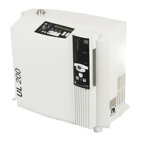
UL 200
Helium Leak Detector
Cat. No.
140 00
141 00
140 01
141 01
140 10
141 10
140 11
141 11
for software version V 2.6
Technical Handbook
T M
142 00
142 10
142 11
Advertisement
Table of Contents


Need help?
Do you have a question about the 141 00 and is the answer not in the manual?
Questions and answers