
Related Manuals for LEYBOLD PHOENIX L300i


Summary of Contents for LEYBOLD PHOENIX L300i
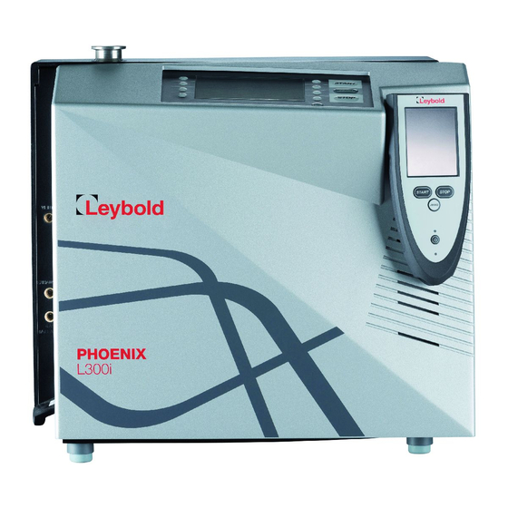
- Page 1 PHOENIX L300i Leak detector Operating Manual GA10218_002_C0 Part numbers 250000V01 250001V01 250002V01 251000V01 251001V01 251100V01 251101V01...
-
Page 2: Table Of Contents
Important safety information Description Design and Function ..............9 1.1.1 Vacuum Diagram PHOENIX L300i ..........10 1.1.2 Vacuum Diagram PHOENIX L300i DRY ........11 1.1.3 Vacuum Diagram PHOENIX L300i MODUL ........ 12 1.1.4 Vacuum Method ................ 13 1.1.5 Partial Flow Method ..............14 1.1.6... - Page 3 3.10.2 Filter & Background ..............73 3.10.3 Mass ..................75 3.10.4 Miscellaneous (Language, Calibration request, Service interval...) 75 3.10.5 Parameter Save/Load ..............78 3.10.6 Monitoring Functions ..............78 3.11 Information ................82 3.11.1 Service ..................83 GA10218_002_C0 - 10/2016 - © Leybold GmbH...
- Page 4 Maintenance Safety Information ..............89 Maintenance Intervals ..............89 Service at Leybold ..............89 Maintenance Work ..............90 4.4.1 Opening of the PHOENIX L300i ..........90 4.4.2 Exchanging the Filter Mats ............91 4.4.3 Exchanging the Oil ..............92 4.4.4 Cleaning ..................
-
Page 5: Important Safety Information
Operating Instructions. Note The Leybold PHOENIX L300i leak detector has been designed for safe and efficient operation when used properly and in accordance with these Operating Instructions. It is the responsibility of the user to carefully read and strictly observe all safety precautions described in this section and throughout the Operating Instructions. - Page 6 Make sure that the mains voltage rating on the PHO- ENIX L300i coincides with the locally available mains voltage. When the PHOENIX L300i is running in closed rooms the exhaust has to be put out of doors so that the oil vapor can not be breathed in.
- Page 7 Definition of Terms The range of the preamplifier and the vacuum ranges are selected automatically. The auto ranging feature of the PHOENIX L300i covers the entire range or leak Auto ranging rates depending on the selected operating mode. Not only the leak rate signal, but also the pressure in the test sample (inlet pressure P1) and the fore vacuum pres- sure (P2) are used for control purposes.
- Page 8 Precision is a measurement mode for the PHOENIX L300i DRY only from an inlet PRECISION pressure < 0,01 mbar. In this mode the PHOENIX L300i DRY has the highest sen- sitivity, the minimum detectable leak rate is 3 · 10 mbar l / s.
-
Page 9: Description
The vacuum is achie- ved with a pumping system that is part of the PHOENIX L300i. In addition the vacuum can be generated by pumps which are set up in parallel to the PHOENIX L300i. -
Page 10: Vacuum Diagram Phoenix L300I
Description Another operating mode of the PHOENIX L300i is the Sniffer mode which can only be used when a sniffer line (See Chapter 1.1.6) is hooked up. 1.1.1 Vacuum Diagram PHOENIX L300i The vacuum diagram below shows the major components inside the PHOENIX L300i. -
Page 11: Vacuum Diagram Phoenix L300I Dry
1.1.2 Vacuum Diagram PHOENIX L300i DRY The PHOENIX L300i DRY has a diaphragm pump as fore vacuum pump, making it suitable for applications where oil sealed systems can not be used. Furthermore the PHOENIX L300i DRY contains one more valve, the valve 4b. This valve opens step by step to regulate the inlet pressure into the turbo pump. -
Page 12: Vacuum Diagram Phoenix L300I Modul
1.1.3 Vacuum Diagram PHOENIX L300i MODUL The PHOENIX L300i MODUL has no roughing pump integrated as the other models. Therefore it can be used with an external pump only. This pump can be oil sealed or a dry version with a roughing capacity between 2.5 and 65 m /h. -
Page 13: Vacuum Method
Because of the higher base pressure of the diaphragm pump the switching from GROSS to FINE mode of the PHOENIX L300i DRY is done by the valve V4b. When the pressure drops below 3,5 mbar the valves V1 and V2b will be close and V4b... -
Page 14: Partial Flow Method
PHOENIX L300i dry and PHOENIX L300i MODUL also. However, in such a case the PHOENIX L300i will not be able to make measurements already at an inlet pressure of 1000 mbar. -
Page 15: Technical Data
To get down to the minimum detected leak rate range some conditions must be fulfilled: PHOENIX L300i has to run at least 20 minutes Ambient conditions must be stable (temperature, no vibration/accelerations.) The part under test has been evacuated long enough without using the zero func-... - Page 16 Permissible ambient temperature (during operation) +10 °C … +40 °C Permissible storage temperature -10 °C … +60 °C Maximum relative humidity 80% (up to 31°C) linear decreasing to 50% at 40°C Max. permissible height above sea level 2000 m (during operation) GA10218_002_C0 - 10/2016 - © Leybold GmbH...
-
Page 17: Technical Data Phoenix L300I Dry
To get down to the minimum detected leak rate range some conditions must be fulfilled: PHOENIX L300i has to run at least 20 minutes Ambient conditions must be stable (temperature, no vibration/accelerations.) The part under test has been evacuated long enough without using the zero func-... - Page 18 Permissible ambient temperature (during operation) +10 °C … +40 °C Permissible storage temperature -10 °C … +60 °C Maximum relative humidity 80% (up to 31°C) linear decreasing to 50% at 40°C Maximum permissible height above sea level 2000 m (during operation) GA10218_002_C0 - 10/2016 - © Leybold GmbH...
-
Page 19: Technical Data Phoenix L300I Modul
To get down to the minimum detected leak rate range some conditions must be fulfilled: PHOENIX L300i has to run at least 20 minutes Ambient conditions must be stable (temperature, no vibration/accelerations.) The part under test has been evacuated long enough without using the zero func-... - Page 20 Ambient conditions Permissible storage temperature -10 °C … +60 °C Maximum relative humidity 80% (up to 31°C) linear decreasing to 50% at 40°C Maximum permissible height above sea level 2000 m (during operation) GA10218_002_C0 - 10/2016 - © Leybold GmbH...
-
Page 21: Dimensional Drawings
Description 1.3.4 Dimensional Drawings Abmaße PHOENIX L300i Familie in mm und inch. (in Klammern) Dimensions PHOENIX L300i family in mm and inches (in brackets). Fig. 5 Dimensions PHOENIX L300i GA10218_002_C0 - 10/2016 - © Leybold GmbH... - Page 22 Description Abmessungen PHOENIX L300i Familie in mm und inch. (in Klammern) Dimensions PHOENIX L300i family in mm and inches (in brackets) Fig. 6 Dimensions PHOENIX L300i side view GA10218_002_C0 - 10/2016 - © Leybold GmbH...
- Page 23 Description Abmessungen PHOENIX L300i in mm und inch (in Klammern). Dimensions PHOENIX L300i in mm and inches (in brackets). Fig. 7 Dimensions PHOENIX L300i MODUL GA10218_002_C0 - 10/2016 - © Leybold GmbH...
-
Page 24: Ordering Information
- Radio transmitter - mounting parts Radio transmitter for remote control 252015V01 Spray gun with hose 16555 Set of connection plugs 20099024 Partial flow system (PHOENIX L300i and PHOENIX 14020 L300i MODUL) Adapter USB/RS232 800110V0103 GA10218_002_C0 - 10/2016 - © Leybold GmbH... - Page 25 Description Sniffer line Sniffer line With the use of a sniffer line the PHOENIX L300i can easily be converted to a sniffer leak detector. Available versions: SL300: 4 m SL301: 4 m and 10 m For further information on the sniffer lines SL300 and SL301 see the enclosed manuals.
-
Page 26: Default Settings
Leak rate external test leak (vacuum): 1E-7 mbar l/s Leak rate external test leak (sniffer): 1E-5 mbar l/s Vent delay: 2 seconds Automatic purge (PHOENIX L300i DRY and PHOENIX L300i MODUL only) Pressure: mbar Minimum volume: Beep: Maximum evacuation time:... -
Page 27: Installation
(sniffer mode). The PHOENIX L300i is to be used for leak detection only. It must not be used as a pumping system (esp. pumping aggressive or humid gases.) - Page 28 The voltage must be in the range 230V (+/- 5%), 115V (+/- 5%) or 100V (+/- 5%) depending on the version. The mains voltage rating for the PHOENIX L300i can be read off from the name plate beneath the mains socket Fig.
-
Page 29: Connection For The Controller Signal And Accessories
Assignment +24 V, constantly applied, power supply for the Leybold partial flow valve or sniffer line. +24V switched by the PHOENIX L300i for an external venting valve 4, 5, 6, 7, 8 These pins are used in connection with accessories. - Page 30 Installation Digital In (Control 2) Digital In (CONTROL2) These inputs can be used to control the PHOENIX L300i with a programmable logic control (PLC). The contacts are numbered from bottom to top. Caution Maximum input voltage 35V. Assignment PLC in free selectable...
- Page 31 Remote control REMOTE2 REMOTE2 Through this interface the PHOENIX L300i is controlled wirelessly via Bluetooth or WLAN. The Bluetooth transmitter connects to the remote control RC310 WL. The WLAN module provides the connection to Apple I-Pad or other handheld devices.
-
Page 32: Vacuum Connections
(see Chapter.Exhaust Oil Filter). When the PHOENIX L300i is running in closed rooms the exhaust has to be put out-of-doors using the provided adapter. So the oil steams that are harmful to health are lead off. With the provided connection a hose line can be connected to the exhaust of the PHOENIX L300i and lead off. - Page 33 Connection of external pumps The PHOENIX L300i MODUL offers two possibilities to connect the external fore vacuum pump to the DN 25 KF flange. One on the side of the PHOENIX L300i or one in the bottom (measurements see Fig. 5 Fig.
-
Page 34: Operation
Operation Purge gas/Gas ballast Media Compatibility/Purge Gas The PHOENIX L300i is a leak detector for helium and hydrogen. Only air and clean gases must be used with the PHOENIX L300i. The leak detector is not suitable for - pumping liquids or gases containing dust... -
Page 35: The Display In Run-Up Mode
This function can be chosen automatically for the PHOENIX L300i MODUL. Every time the unit changes into standby mode the purge starts automatically for 20 seconds. -
Page 36: Call For Calibration
(White black background.) Trigger 2 see: Trigger 1 Trigger 3 see: Trigger 1 Warning triangle Please refer to Chapter 5 Working mode VAC or SNIFF indicate which working mode was selected GA10218_002_C0 - 10/2016 - © Leybold GmbH... -
Page 37: Measurement Mode With Bargraph
PHOENIX L300i, how to measure and how to carry out an internal calibra- tion. If anything unexpected happens during the initial operation or the leak detector acts in a strange way the PHOENIX L300i can be switched off by the mains switch at any time. GA10218_002_C0 - 10/2016 - © Leybold GmbH... - Page 38 5. Press the START button. The inlet will be evacuated and if the inlet pressure drops below 15 mbar a measured leak rate will be displayed. 6. Press the STOP button, the PHOENIX L300i will go to standby. If you press STOP a few seconds the inlet of the PHOENIX L300i will be vented.
-
Page 39: Control Panel
20. Remove the test object and put on a blind flange on the inlet port. Switch off Switch off 21. Switch off the PHOENIX L300i if the unit is in STANDBY or VENTED mode by using the mains switch Fig. - Page 40 Fig. 12 /9 is the communication interface to the operator. It displays the leak rates, the status report of the PHOENIX L300i, messages, warnings and errors. With the soft keys no.1 to no. 8 various functions which are shown in the...
- Page 41 If the menu is opened during the current session the operator will lead to the last screen before the menu was left. Pushing the MENU button again leads back to the screen of the previous working mode. The software shows the last screen that was used before. GA10218_002_C0 - 10/2016 - © Leybold GmbH...
- Page 42 16) . Please consider that the first digit is displayed inverted. If not please change the digit with (softkey no. 8) or (softkey no. 4). With the soft key no. 4 (Fig. 12) the chosen value can be selected. GA10218_002_C0 - 10/2016 - © Leybold GmbH...
- Page 43 Operation Fig. 15 Numerical entry of the trigger level, sample of the digit In the submenu press 3 (soft key no.4) Fig. 16 Fig. 16 Trigger level, change of the first digit GA10218_002_C0 - 10/2016 - © Leybold GmbH...
-
Page 44: Interfaces
Define PLC inputs (Control 2, Digital in) Customer defined selection for PLC inputs Softkey 7: Scaling recorder outputs Selection for the scaling of the recorder output Softkey 8: PLC sample rate Selection of the PLC sample rate GA10218_002_C0 - 10/2016 - © Leybold GmbH... - Page 45 0,45 0,52 0,97 2,6 5,97 8,2 8,65 mbar,atm 0,75 7,5 Torr 7,5E 7,5E 7,5E Fig. 17 Recorder output: Pirani PHOENIX L300i, P1 and P2. The complete characteristic Pirani line is shown in the appendix. GA10218_002_C0 - 10/2016 - © Leybold GmbH...
- Page 46 P1 Pirani PHOENIX L300i The inlet pressure P1 of the PHOENIX L300i will be shown logarithmic. Fig. 17 P2 Pirani PHOENIX L300i The fore vacuum pressure P2 of the PHOENIX L300i will be shown log- arithmic. Fig. 17 P1 (L200) The setting for the inlet pressure P1 is identical with those of the L200, i.e.
- Page 47 Fig. 19 Recorder output: Leak rate exponent Recorder output leak rate logarithmic Mantissa Fig. 20 Recorder output: Leak rate mantissa 10 10 mbarl/s, Pam•/s Torrl/s, sft•/yr oz/yr, g/a Fig. 21 Recorder output: Leak rate logarithmic, default setting GA10218_002_C0 - 10/2016 - © Leybold GmbH...
- Page 48 The following digital out signals are selectable. Trigger 1; Trigger 2 and 3 analog Trigger 1 Is open in case Trigger Level 1 is exceeded or the machine is not in condition of GA10218_002_C0 - 10/2016 - © Leybold GmbH...
- Page 49 Open when emission is on. Define PLC inputs Define PLC inputs Main menu > Settings > Interfaces > Define PLC inputs These inputs can be used to control the PHOENIX L300i with a programmable logic control (PLC). Maximum input voltage 35V. Caution...
- Page 50 Change from high to low: approve that external test leak is closed and leak rate signal is stable. Signals at these inputs are only accepted if the location of control is set to „PLC“, “All“ or „Local and PLC“. GA10218_002_C0 - 10/2016 - © Leybold GmbH...
-
Page 51: Operation
Main menu > Settings > Interfaces > PLC Sample rate Softkey 2: Decreasing the PLC sample rate down to the minimum of 10 ms. This might be necessary if exchanging an L200 to the PHOENIX L300i to stay compatible. Softkey 3: Increasing the PLC sample rate to the maximum of 100 ms. -
Page 52: Main Menu
Settings of internal machine parameters. Please refer to Chapter 3.10. Information Information PHOENIX L300i (electrical and vacuum data) and service menu. Please refer to Chapter 3.11. Access Control Access restrictions. Please refer to Chapter 3.12. GA10218_002_C0 - 10/2016 - © Leybold GmbH... - Page 53 Pressure limits for vacuum mode Information View settings View internal data Vacuum diagram View error list Calibration history Calibration factors Service Access Control Access to CAL function Change Device-PIN Change Menu-Pin Zero Fig. 23 Overview menu structure GA10218_002_C0 - 10/2016 - © Leybold GmbH...
-
Page 54: View
( and ) it can be determined how many decades the bargraph and Y-axis are covered. Usually a logarithmic scale is recommended because leak rates may change easily over several decades. Default setting is logarithmic with 4 decades. GA10218_002_C0 - 10/2016 - © Leybold GmbH... -
Page 55: Display-Range Auto/Manual
If linear scale is selected, the lower limit is always zero. The upper limit is only a default value. You can change this on the measurement screen with the Soft Key 6 and 7 if you have chosen manual display ranging. GA10218_002_C0 - 10/2016 - © Leybold GmbH... -
Page 56: Time Axis
Switch off the PHOENIX L300i and turn it on again. During the run-up phase press the key no. 3 or 7 so long until the display can be read properly again. This setting is saved to the EPROM only after confirming this through the contrast menu. -
Page 57: Background In Standby
Sources for residual gas are air or absorbed gases from the inner surfaces of the PHOENIX L300i. This internal background will never dis- appear totally. Very clean systems which have been pumped for a long time will show a background in the 10 mbar l/s range. -
Page 58: Mode
Return to the main menu without any changes of the present settings. Sniff The sniffer mode will be used. Vacuum The vacuum mode will be used. Save the settings and return to the previous menu. GA10218_002_C0 - 10/2016 - © Leybold GmbH... -
Page 59: Trigger & Alarms
Trigger 1, 2 and Trigger 3 are programmable switching thresholds. When these thresholds will be exceeded the PHOENIX L300i reacts as follows: Display In the status line of the display the signs for Trigger 1, 2 and Trigger 3 are displayed inverted if the leak rate exceeds (becomes higher than) the programmed value. -
Page 60: Trigger Level 2
Scroll up to select a pressure unit. Softkey 3: Scroll down to select a pressure unit. Softkey 6: Scroll up to select a leak rate unit. Softkey 7: Scroll down to select a leak rate unit. GA10218_002_C0 - 10/2016 - © Leybold GmbH... -
Page 61: Volume
After pressing START the loudspeaker is activated as soon as the leak rate drops below trigger level 1 or after the entered alarm delay time has elapsed. This setting is only active for the audio alarm types SETPOINT and TRIGGER ALARM (See chapter 3.8.7). GA10218_002_C0 - 10/2016 - © Leybold GmbH... -
Page 62: Audio Alarm Type
The frequency of the acoustic output is proportional to the reading on the bargraph display. The frequency ranges from 300 Hz to 3300 Hz. Please refer to Chapter 3.6.3 for the definition of the number of decades. GA10218_002_C0 - 10/2016 - © Leybold GmbH... -
Page 63: Calibration
In the menu Calibration Fig. 29 the selection between internal and external calibra- tion can be chosen. Please refer to Chapter 3.13 Calibration for a detailed description of the calibration. Fig. 29 Display: Calibration menu GA10218_002_C0 - 10/2016 - © Leybold GmbH... -
Page 64: Settings
Settings like date or time. See Chapter 3.10.4 Parameter save / load Store and load sets of parameters. See Chapter 3.10.5 Monitoring functions Choose functions of protection of the PHOENIX L300i in this mode. See Chap- 3.10.6 GA10218_002_C0 - 10/2016 - © Leybold GmbH... -
Page 65: Vacuum Settings
Setting for the machine factor Softkey 8: Leak rate internal test leak Setting for the internal test leak The menu for the PHOENIX L300i DRY version allows the following vacuum set- Vacuum settings PHOENIX tings which varies to the PHOENIX L300i: L300i DRY... - Page 66 Main menu > Settings > Vacuum settings > Automatic purge Through this menu is it possible to start automatic purge for 20 seconds automatically. This setting is only possible for the PHOENIX L300i MODUL (refer to vacuum set- tings PHOENIX L300i MODUL) Softkey 3: The function automatic purge is off.
- Page 67 This setting is only active in vacuum mode (see Chapter 3.5). Softkey No. 2: GROSS only In this mode the PHOENIX L300i remains at the inlet flange after falling below 15 mbar. When the pressure is increasing over 15 mbar the PHO- ENIX L300i switches automatically into evacuation mode.
- Page 68 Operation If the PHOENIX L300i or the PHOENIX L300i MODUL is used with a par- tial flow system this vacuum mode must be enabled before. The setup for the partial flow mode is described in partial flow setup Softkey No. 7: Normal (default settings) This is the default setting.
- Page 69 Operation The PHOENIX L300i MODUL allows additionally the settings for the forepump (oil sealed or dry) and selectable pumping speed for the forepump. Partial flow setup for the PHOENIX L300i. Partial flow setup PHOENIX L300i Softkey 2: The entry of the nominal pumping speed of the partial flow pump can be decreased.
- Page 70 Settings > Vacuum settings > Vacuum ranges with softkey no. 6 partial flow enable and confirm with the soft key OK. Softkey 2: Pump setup Setting for the forepump if the PHOENIX L300i MODUL is operated with a partial flow system. Softkey 7: Partial flow setup Options for setting up the partial flow system.
- Page 71 At T = endless valve V10 will open when pressing start. At an inlet pres- sure p1 < 15 mbar the PHOENIX L300i switches to measurement mode and display leak rates. This is recommended if it is acceptable to wait for a while until measurement mode is reached and leak rate reading at high inlet pressures are not needed.
- Page 72 Setting between the default value 1 for the sniffer line SL300 or the cor- rection factor (1000) for the use of the Quicktest. For the use of a PHOENIX L300i with a Quicktest the setting for the Quicktest Quicktest setting under Main menu >...
-
Page 73: Filter & Background
If the use of the PHOENIX L300i DRY needs the possibility to shut off this function, fore ex. because of a high helium background in the ambient and no option to connect a hose line with fresh air to the gas ballast port, this function can be shut of here. - Page 74 „Calculate inlet area background“. Softkey 7: internal only (default) With start the PHOENIX L300i defines the internal offset (background) and subtracts this value from the leak rate signal, so that just the leak rate is shown in the display. This setting should be used as standard setting for the PHOENIX L300i.
-
Page 75: Mass
Operation 3.10.3 Mass Main menu > Settings > Mass The requested mass of the measured gas can be selected. The PHOENIX L300i must be in standby mode for changing to another mass. Softkey 2: H (2 amu) Hydrogen with the mass of 2 amu will be measured. - Page 76 Setting for the service interval of the forepump. This setting depends on the use of the PHOENIX L300i but latest after 4000 running hours or one year the oil in the pump should be controlled. See also manual for the Trivac D2,5E which is included in the document folder.
- Page 77 Here you can enter the service interval for the exhaust oil filter. This setting is only filter possible for the PHOENIX L300i. This setting depends on the use and application of your PHOENIX L300i and therefore no recommendations can be given (see chap.
-
Page 78: Parameter Save/Load
Softkey No. 4: Contamination protection Set the switch off limit and enable the function Softkey No. 6: Pressure limits for vacuum mode Setting for the pressure limits between evacuation, Gross and Fine mode. GA10218_002_C0 - 10/2016 - © Leybold GmbH... - Page 79 Main menu > Settings > Surveillance > Contamination Protection If enabled, this mode will cause the PHOENIX to close all inlet valves as soon as the measured leak rate exceeds the programmed limit. Once the START key is GA10218_002_C0 - 10/2016 - © Leybold GmbH...
- Page 80 Decrease change over threshold GROSS-FINE Selectable between 0,2-0,05 mbar (Default value 0,2 mbar). For the PHOENIX L300i DRY and the PHOENIX L300i MODUL the changeover is between 0,1-0,05 mbar (Default value 0,2 mbar). Softkey No. 4 Adjustment for ARGON Selection between air or Argon Softkey No.
- Page 81 Softkey No. 7: Increase change over threshold GROSS-FINE Selectable between 0,05 - 0,2 mbar, respectively 0,05 - 0,1 mbar for PHOENIX L300i DRY and PHOENIX L300i MODUL Pressure limits for sniff Pressure limits for sniff mode mode Main menu > Settings > Monitoring functions > Pressure limits for sniff mode This function is automatically activated in sniff mode.
-
Page 82: Information
Information on measured internal data is provided on 10 screens. Softkey 4: Vacuum diagram The vacuum diagram of the PHOENIX L300i is shown. Here you can see which valves are opened or closed momentarily. See chapter 4.1.1 Softkey 5: View error list The list of occurred errors and warnings will be displayed. -
Page 83: Service
With „Zero at FINE“, the ZERO functions executes automatically as soon as the measuring range FINE is reached for the first time after START. In this mode the ZERO function also can be executed manually via the ZERO button. GA10218_002_C0 - 10/2016 - © Leybold GmbH... -
Page 84: Access To Cal Function
Calibration 3.13.1 Introduction The PHOENIX L300i can be calibrated in two different ways: Internal calibration by means of a built-in test leak external calibration by means of an additional test leak which then is attached to the inlet port or the component under test. -
Page 85: The Calibration Routines
Although the PHOENIX L300i is a very stable inst- rument a calibration is recommended every day with heavy use, or before using the PHOENIX L300i from time to time, to make sure that ambient temperature changes or dirt or other impacts don’t adulterate the measurements. -
Page 86: External Calibration
Fig. 34 Display: External Calibration, Step 2 bargraph display shows a signal which must not vary much. If so please press OK (Soft Key no. 8). Fig. 35 Display: External Calibration, Step 3 GA10218_002_C0 - 10/2016 - © Leybold GmbH... - Page 87 When the signal is stable confirm with o.k. Fig. 38 Display: External Calibration, Step 6 PHOENIX L300i shows the old and the new calculated calibration factor. Fig. 39 Display: External Calibration, Step 7 GA10218_002_C0 - 10/2016 - © Leybold GmbH...
-
Page 88: Switching Off/Shutting Down
3.14 Switching Off/Shutting Down The PHOENIX L300i can be switched off any time by using the mains switch. The turbo pump will be decelerated automatically. It is recommended to put the leak detector into standby and vented mode. Approximately after 30 seconds the turbo pump is decelerated sufficient to move the PHOENIX L300i. -
Page 89: Maintenance
Only Leybonol LVO 310 (Cat. no. L31001) must be used in the TRIVAC D2,5E in the PHOENIX L300i. The monthly interval for the check is just a nominal period. If the PHOENIX L300i is used heavily, in particular in sniffer mode, then this check should be performed more frequently. -
Page 90: Maintenance Work
To open the PHOENIX L300i please follow the next steps: 1. Switch the PHOENIX L300i off. 2. Pull the mains cord on the PHOENIX L300i. 3. Separate the PHOENIX L300i from other vacuum components at the test port. GA10218_002_C0 - 10/2016 - © Leybold GmbH... -
Page 91: Exchanging The Filter Mats
Maintenance Fig. 41 Opening of the mechanical hood 4. Turn the PHOENIX L300i so that it is orientated in the same way as shown in Fig. 5. Use two flat blade screw drivers and insert these into the openings (Fig. -
Page 92: Exchanging The Oil
4.4.4 Cleaning The housing of the PHOENIX L300i is made of painted plastic parts. Thus for the purpose of cleaning, only such agents should be used which are generally also used for other painted or plastic surfaces (mild household cleaning agents, for example). - Page 93 6. After having exchanged the fuse (s) press the lid of the mains socket firmly back 7. Insert the mains cord into the PHOENIX L300i and switch the instrument on. Beside these mains fuses several internal circuits are fused separately. These fuses are listed in the following table.
-
Page 94: Exhaust Oil Filter
Fig. 42 Assembly fuses 4.4.6 Exhaust Oil Filter After using the PHOENIX L300i for a longer time there can be oil accumulated from the pump. In this case please do the following: 1. Switch off the PHOENIX L300i. 2. Remove the mechanical cover according to Chapter 4.4.1. -
Page 95: Calibrated Leak Tl7
Calibrated Leak TL7 The Calibrated leak TL7 with the helium reservoir is used for alignment of the mass spectrometer in the PHOENIX L300i as well as for calibration the leak rate indica- tion. It is equipped with a solenoid valve which is actuated via the control electronics of the PHOENIX L300i. -
Page 96: Troubleshooting
The PHOENIX L300i will indicate a message on the LC display and will remain in the standby or the measurement mode. Warning messages will remain on the LC display until the warning has been acknowledged by pressing „OK“... - Page 97 – Reference voltage UREF on the MSV board XT7/1 is too high, U > 5 V. – DC/DC converter on the MSV board is defective. – 24V power supply voltage of the main power supply is defective or stressed to much. GA10218_002_C0 - 10/2016 - © Leybold GmbH...
- Page 98 W45 Emission for cathode 1 can not Signal MSIBE on MSV board is not active. Emission for cathode 1 can not be be switched on! switched on. PHOENIX L300i switches to cathode 2. Please order a new ion source. Cathode 1 is defective MSV board is defective GA10218_002_C0 - 10/2016 - ©...
- Page 99 W46 Emission for cathode 2 can can Signal MSIBE on MSV board is not active. Emission for cathode 2 can not be not be switched. switched on. PHOENIX L300i switches to cathode 1. Order a new ion source. Cathode 2 is defective.
- Page 100 Fore vacuum or high-vacuum pressure to high: Reduce the inlet pressure of the PHOENIX L300i Fan defective: Replace the fan Ambient temperature too high: Feed cooler air to the PHOENIX L300i Bearing defective: Inform Leybold service for repair E67 TMP error: Short circuit in TMP- Short circuit in the pump’s motor or the connecting cable...
- Page 101 Maximum temperature for the converter has been exceeded. ter too high (>75°C) Ambient temperature too high: Feed cooler air to the PHOENIX L300i Fan defective: Replace the fan Fore vacuum or high-vacuum pressure to high: reduce the inlet pressure of...
- Page 102 Writing access was interrupted. Please check all adjustments. check your settings! An software update was done. In this case the notice can be ignored. When warning comes up again after powering up the EEPROM might be faulty. GA10218_002_C0 - 10/2016 - © Leybold GmbH...
-
Page 103: Waste Disposal
Separate clean components according to their materials, and dispose of these accordingly. We offer this service. Further details are available on request. When sending us any equipment, observer the regulations given in Section Service at Leybold. GA10218_002_C0 - 10/2016 - © Leybold GmbH 103... - Page 104 Waste Disposal GA10218_002_C0 - 10/2016 - © Leybold GmbH...
-
Page 105: Certificates
Certificates Certificates Fig. 43 GA10218_002_C0 - 10/2016 - © Leybold GmbH 10... - Page 106 Certificates GA10218_002_C0 - 10/2016 - © Leybold GmbH...
- Page 107 Trigger & Alarms Gas ballast connection Troubleshooting GASBALLAST Turbo molecular pump gross USB interface Inlet Port Internal Calibration Vacuum ranges Vacuum settings List of Errors & Warnings VENT mains socket ZERO Button GA10218_002_C0 - 10/2016 - © Leybold Vacuum106...
- Page 108 Appendix GA10218_002_C0 - 10/2016 - © Leybold Vacuum...
- Page 109 Appendix GA10218_002_C0 - 10/2016 - © Leybold Vacuum 108...
- Page 110 Appendix GA10218_002_C0 - 10/2016 - © Leybold Vacuum...
- Page 111 Appendix GA10218_002_C0 - 10/2016 - © Leybold Vacuum110...
- Page 112 Sales and Service Germany Great Britain America Leybold Japan Co., Ltd. Tsukuba Technical Service Center 1959, Kami-yokoba Leybold UK LTD. Leybold GmbH Tsukuba-shi, Ibaraki-shi 305-0854 Unit 9 Sales, Service, Support Center (3SC) Japan Silverglade Business Park Bonner Strasse 498 Leybold USA Inc.
Need help?
Do you have a question about the PHOENIX L300i and is the answer not in the manual?
Questions and answers