Table of Contents
Advertisement
© 2018 Lennox Industries Inc.
Dallas, Texas USA
Contents
Unit Dimensions - inches (mm) ......................................2
EL195UHNE Gas Furnace .............................................3
Shipping and Packing List ..............................................3
Safety Information ..........................................................3
Use of Furnace as Construction Heater .........................4
General ...........................................................................5
Combustion, Dilution & Ventilation Air ............................5
Shipping Bolt Removal ...................................................8
Installation - Setting Equipment ......................................8
Filters ............................................................................13
Duct System .................................................................13
Pipe Fittings Specifications...........................................13
Joint Cementing Procedure ..........................................16
INSTALLATION
INSTRUCTIONS
EL195UHNE
ELITE
SERIES GAS FURNACE
®
UPFLOW / HORIZONTAL AIR DISCHARGE
507758-02
02/2018
Supersedes 507758-01
THIS MANUAL MUST BE LEFT WITH THE
HOMEOWNER FOR FUTURE REFERENCE
This is a safety alert symbol and should never be
ignored. When you see this symbol on labels or in man-
uals, be alert to the potential for personal injury or death.
As with any mechanical equipment, contact with sharp
sheet metal edges can result in personal injury. Take
care while handling this equipment and wear gloves and
protective clothing.
Improper installation, adjustment, alteration, service
or maintenance can cause property damage, personal
injury or loss of life. Installation and service must be
performed by a licensed professional HVAC installer or
equivalent, service agency, or the gas supplier.
Venting Practices ..........................................................16
Vent Piping Guidelines .................................................17
Gas Piping ....................................................................36
Electrical .......................................................................38
Ignition Control .............................................................41
Unit Start-Up .................................................................41
Gas Pressure Adjustment .............................................44
Proper Combustion.......................................................44
High Altitude Information ..............................................44
Testing for Venting and Combustion Air........................45
Service..........................................................................46
Repair Parts List ...........................................................48
Start-Up & Performance Check List .............................49
Page 1
CAUTION
WARNING
Advertisement
Table of Contents

Related Manuals for Lennox EL195UH040NE36B


Summary of Contents for Lennox EL195UH040NE36B
-
Page 1: Table Of Contents
INSTALLATION INSTRUCTIONS EL195UHNE © 2018 Lennox Industries Inc. Dallas, Texas USA ELITE SERIES GAS FURNACE ® UPFLOW / HORIZONTAL AIR DISCHARGE 507758-02 02/2018 Supersedes 507758-01 THIS MANUAL MUST BE LEFT WITH THE HOMEOWNER FOR FUTURE REFERENCE This is a safety alert symbol and should never be ignored. -
Page 2: Unit Dimensions - Inches (Mm)
23-1/2 (83) (19) (19) (597) Bottom Return Bottom Return Air Opening Air Opening FRONT VIEW SIDE VIEW Model in (mm) in (mm) in (mm) EL195UH040NE36B 17-1/2 (446) 16-3/8 (416) (406) EL195UH060NE36B EL195UH080NE48C (553) 19-7/8 (505) 19-1/2 (495) EL195UH100NE60C Page 2... -
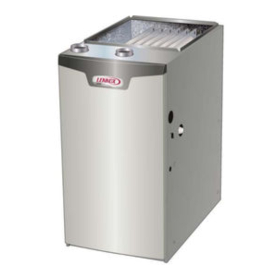
Page 3: El195Uhne Gas Furnace
EL195UHNE Gas Furnace Shipping and Packing List Package 1 of 1 contains The EL195UHNE Category IV gas furnace is shipped ready for installation in the upflow or horizontal position. The furnace is 1 - Assembled EL195UHNE unit shipped with the bottom panel in place. The bottom panel must 1 - Bag assembly containing the following: be removed if the unit is to be installed in horizontal or upflow 1 - Snap bushing... -
Page 4: Use Of Furnace As Construction Heater
Use of Furnace as Construction Heater partment. With a parallel flow arrangement, a damper (or Lennox does not recommend the use of EL195UHNE other means to control the flow of air) must adequately units as a construction heater during any phase of con- prevent chilled air from entering the furnace. -
Page 5: General
• Air filters must be replaced upon construction com- WARNING pletion. Insufficient combustion air can cause headaches, • The input rate and temperature rise must be set per nausea, dizziness or asphyxiation. It will also cause the furnace rating plate. excess water in the heat exchanger resulting in rusting •... - Page 6 In Canada, refer to the CSA B149 installation codes. Even a small leak around the base of the unit at the plat- form or at the return air duct connection can cause a po- CAUTION tentially dangerous negative pressure condition. Air for combustion and ventilation can be brought into the con- Do not install the furnace in a corrosive or contaminated fined space either from inside the building or from outside...
- Page 7 EQUIPMENT IN CONFINED SPACE - ALL AIR FROM OUTSIDE EQUIPMENT IN CONFINED SPACE (Inlet Air from Crawl Space and Outlet Air to Outside) (Inlet Air from Ventilated Crawlspace and Outlet Air to Outside) VENTILATION LOUVERS Roof Terminated (Each end of attic) Exhaust Pipe ROOF TERMINATED EXHAUST PIPE...
-
Page 8: Shipping Bolt Removal
flexible mounting leg). See figure 10. The bolt and washer EQUIPMENT IN CONFINED SPACE - ALL AIR FROM OUTSIDE must be removed before the furnace is placed into oper- (All Air Through Ventilated Attic) ation. After the bolt and washer have been removed, the rigid leg will not touch the blower housing. - Page 9 SETTING EQUIPMENT Unit must be level side-to-side. Unit may be positioned from level to 1/2” toward the front to aid in draining. UPFLOW APPLICATION UNIT FRONT UNIT FRONT AIR FLOW 1/2” max. SIDE VIEW SIDE VIEW FRONT VIEW HORIZONTAL APPLICATION UNIT FRONT 1/2”...
- Page 10 Return Air Guidelines WARNING Return air can be brought in through the bottom or either Improper installation of the furnace can result in personal side of the furnace installed in an upflow application. If the furnace is installed on a platform with bottom return, make injury or death.
- Page 11 Optional Return Air Base CONDENSATE (Upflow Applications Only) TRAP FURNACE FRONT 23 (584) 3−1/4 IF BASE Overall (83) IS USED (Maximum) Minimum WITHOUT 11 (279) IAQ CABINET, Maximum 22−7/16 INDOOR AIR A SINGLE Unit side return air 14 (356) (570) QUALITY RETURN AIR Opening...
- Page 12 18, or install the furnace on a platform, as shown in figure 19. A horizontal suspension 6 - Continue with exhaust, condensate and intake piping kit (51W10) may be ordered from Lennox or use equiva- installation according to instructions. lent.
-
Page 13: Filters
If a filter is installed, size the specifications provided by the filter manufacturer against return air duct to fit the filter frame. the data given in the appropriate Lennox Product Specifications bulletin. Additional information is provided in Service and Application Note ACC002 (August 2000). - Page 14 Duct System and Proper Installation SUPPLY SUPPLY Figure 20 TABLE 2 Pipe & Fittings Specifications All pipe, fittings, primer and solvent cement must conform PIPING AND FITTINGS SPECIFICATIONS with American National Standard Institute and the Ameri- Schedule 40 PVC (Pipe) D1785 can Society for Testing and Materials (ANSI/ASTM) stan- Schedule 40 PVC (Cellular Core Pipe)
- Page 15 Use PVC primer and solvent cement or ABS solvent ce- Canadian Applications Only - Pipe, fittings, primer and sol- ment meeting ASTM specifications, refer to Table 2. As an vent cement used to vent (exhaust) this appliance must alternate, use all purpose cement, to bond ABS, PVC, or be certified to ULC S636 and supplied by a single manu- CPVC pipe when using fittings and pipe made of the same facturer as part of an approved vent (exhaust) system.
-
Page 16: Joint Cementing Procedure
Joint Cementing Procedure Venting Practices All cementing of joints should be done according to the specifications outlined in ASTM D 2855. Piping Suspension Guidelines DANGER SCHEDULE 40 PVC - 5' DANGER OF EXPLOSION! all other pipe* - 3' Fumes from PVC glue may ignite during system check. Allow fumes to dissipate for at least 5 minutes before placing unit into operation. -
Page 17: Vent Piping Guidelines
Figure 22 Vent Piping Guidelines Exhaust Piping (Figures 23, 26 and 27) NOTE - Lennox has approved the use of DuraVent® and The vent adapter must be attached to the exhaust cou- Centrotherm manufactured vent pipe and terminations as pling on the furnace top panel. Use provided bands. See an option to PVC. - Page 18 NOTE - The exhaust collar on all models is sized to ac- Use the following steps to correctly size vent pipe diam- eter. commodate 2” Schedule 40 vent pipe. In horizontal ap- plications, any transition to exhaust pipe larger than 2” Pipe Size Process must be made in vertical runs of the pipe.
- Page 19 TABLE 5 NOTE - Size intake and exhaust pipe length separately. Values in table are for Intake OR Exhaust, not combined total. Both Intake and Exhaust must be same pipe size. NOTE - Additional vent pipe and elbows used to terminate the vent pipe outside the structure must be included in the total vent length calculation.
- Page 20 TABLE 6 Maximum Allowable Exhaust Vent Lengths With Furnace Installed in a Closet or Basement Using Ventilated Attic or Crawl Space For Intake Air in Feet NOTE - Additional vent pipe and elbows used to terminate the vent pipe outside the structure must be included in the total vent length calculation.
- Page 21 TYPICAL EXHAUST AND INTAKE PIPE CONNECTIONS IN UPFLOW DIRECT OR NON-DIRECT VENT APPLICATIONS EXHAUST EXHAUST INTAKE 2” 2” 2” 2” 3” Appliance TRANSITION Appliance Adaptor 2” Adaptor DO NOT transition *2” from smaller to larger 2” 3” pipe in horizontal runs *2”...
- Page 22 Intake Piping TYPICAL AIR INTAKE PIPE CONNECTIONS The EL195UHNE furnace may be installed in either direct UPFLOW NON−DIRECT vent or non-direct vent applications. In non-direct vent VENT APPLICATIONS applications, when intake air will be drawn into the furnace from the surrounding space, the indoor air quality must be considered and guidelines listed in Combustion, Dilution and Ventilation Air section must be followed.
- Page 23 General Guidelines for Vent Terminations CAUTION In Non-Direct Vent applications, combustion air is taken If this unit is being installed in an application with from indoors and the flue gases are discharged to the out- combustion air coming in from a space serviced by an doors.
- Page 24 TABLE 7 Maximum Allowable Exhaust Vent Pipe Length (in ft.) Without Insulation In Unconditioned Space For Winter Design Temperatures Single - Stage High Efficiency Furnace Unit Input Size Winter Design Vent Temp °F (°C) Pipe Diam 32 to 21 2 in (0 to -6) 3 in 20 to 1...
-
Page 25: Vent Termination Clearances
‡ Permitted only if veranda, porch, deck or balcony is fully open on a minimum of two sides beneath the floor. Lennox recommends avoiding this location if possible. Figure 33... - Page 26 ‡ Permitted only if veranda, porch, deck or balcony is fully open on a minimum of two sides beneath the floor. Lennox recommends avoiding this location if possible. Figure 34 Page 26...
- Page 27 Details of Intake and Exhaust Piping Terminations for 3”(76mm) MAX. Direct Vent Installations Inches(mm) NOTE - In Direct Vent installations, combustion air is taken UNCONDITIONED from outdoors and flue gases are discharged to outdoors. ATTIC SPACE 8” (203mm) MIN NOTE - Flue gas may be slightly acidic and may adverse- ly affect some building materials.
-
Page 28: Front View
7 - If intake and exhaust piping must be run up a side FIELD-PROVIDED wall to position above snow accumulation or other QUIRED TO ADAPT obstructions, piping must be supported. At least one LARGER VENT PIPE bracket must be used within 6” from the top of the SIZE TO TERMINATION. - Page 29 FIELD FABRICATED WALL TERMINATION NOTE − FIELD−PROVIDED REDUCER MAY BE 2” (51mm) 3” (76mm) REQUIRED TO ADAPT LARGER VENT PIPE SIZE Vent Pipe Vent Pipe TO TERMINATION A− Minimum clearance above grade or average 12” (305 mm) 12” (305 mm) snow accumulation B−...
- Page 30 Basement Floor Figure 44 Crawl Space and Extended Horizontal Venting Lennox provides kit 51W18 (USA) kit 15Z70 (Canada) to install 2” or 3” PVC exhaust piping through the floor joists KIT 51W18 and into the crawl space. See figure 46. This kit can also...
- Page 31 55. Route the condensate line to an open drain. Heating cable kit is available from Lennox in various Condensate line must maintain a 1/4” downward lengths; 6 ft. (1.8m) - kit no. 26K68 and 24 ft. (7.3m) - slope from the furnace to the drain.
- Page 32 CONDENSATE TRAP LOCATIONS Condensate Trap With Optional Overflow Switch (Unit shown in upflow position with remote trap) From Evaporator Coil HorizontalFurnace4” Min. to 5” Max.above FieldProvidedVent condensatedrain connection) Min. 1” Above Condensate Drain Connection 1” Min. 2” Max. FurnaceCondensate *5’ max. DrainConnection PV C PipeOnly Optional...
- Page 33 Furnace with Evaporator Coil Using a Separate Drain (Unit shown in horizontal left-hand discharge position) Field Provided Vent Evaporator (4” min. to 5” max. above Coil condensate connection) 4”min 5”max 5’ max. PVC Pipe Only Condensate Drain Connection (Trap at coil is optional) Drain Pan Piping from furnace and evaporator coil must slope down a minimum 1/4”...
- Page 34 TRAP / DRAIN ASSEMBLY USING 1/2” PVC OR 3/4” PVC Optional Condensate Drain Connection Adapter 3/4 inch slip X 3/4 inch mpt (not furnished) 90° Street Elbow 3/4 inch PVC (not furnished) Adapter 3/4 inch slip X 3/4 inch mpt (not furnished) Condensate Drain Connection In Unit 1 (25 mm) Min.
- Page 35 6 - In some localities, codes may require installation of a Gas Piping manual main shut-off valve and union (furnished by Gas supply piping should not allow more than 0.5”W.C. installer) external to the unit. Union must be of the drop in pressure between gas meter and unit.
-
Page 36: Gas Piping
Right Side Piping MANUAL MAIN SHUT-OFF VALVE GROUND JOINT UNION DRIP LEG Gas Valve FIELD PROVIDED AND INSTALLED NOTE - BLACK IRON PIPE ONLY TO BE ROUTED INSIDE OF CABINET Figure 57 Horizontal Applications Possible Gas Piping Configurations Horizontal Application MANUAL MAIN SHUT-OFF Right-Side Air Discharge... - Page 37 TABLE 9 Gas Pipe Capacity - ft3/hr (m3/hr) Nominal Internal Length of Pipe - feet (m) Iron Pipe Diameter Size Inches inches (3.048) (6.096) (9,144) (12,192) (15.240) (18.288) (21.336) (24.384) (27.432) (30,480) (mm) (mm) .622 (12.7) (17.799) (4.87) (3.34) (2.69) (2.29) (2.03) (1.84)
-
Page 38: Electrical
The unit is equipped with a field make-up box. The make- Electrical up box may be moved to the right side of the furnace to fa- cilitate installation. Secure the excess wire to the existing ELECTROSTATIC DISCHARGE (ESD) harness to protect it from damage. Precautions and Procedures Refer to figure 60 for field wiring, schematic wiring dia- CAUTION... - Page 39 Accessory Terminals Indoor Blower Speeds 1 - When the thermostat is set to “FAN ON,” the indoor One line voltage “EAC” 1/4” spade terminal is provided on blower will run continuously on the fan speed (FAN) the furnace integrated control. See figure 61 for integrated when there is no cooling or heating demand.
- Page 40 TYPICAL EL195UHNE WIRING DIAGRAM Figure 60 Page 40...
-
Page 41: Unit Start-Up
Electrical INTEGRATED CONTROL FOR YOUR SAFETY READ BEFORE OPERATING (Automatic Hot Surface Ignition System) WARNING Do not use this furnace if any part has been underwater. A flood-damaged furnace is extremely dangerous. Attempts to use the furnace can result in fire or explosion. Immediately call a qualified service technician to inspect the furnace and to replace all gas controls, control system parts, and electrical parts that have been wet or... - Page 42 TABLE 11 RED LED Diagnostic Codes / Status of Furnace Flash Code No power to control or board fault detected Heartbeat Normal Operation - Idle, Continuous Fan, Cool Continuous Rapid Flash Call For Heat / Burner Operation Reverse Line Voltage Polarity Improper Earth Ground Burner failed to light, or lost flame during heat demand Low Flame Signal - check flame sensor...
-
Page 43: Ignition Control
Priming Condensate Trap 9 - Replace the access panel. 10- Turn on all electrical power to the unit. The condensate trap should be primed with water prior 11- Set the thermostat to desired setting. to start-up to ensure proper condensate drainage. Either pour 10 fl. -
Page 44: Gas Pressure Adjustment
2 - Start unit and allow 5 minutes for unit to reach steady Gas Pressure Adjustment state. Gas Flow (Approximate) 3 - After allowing unit to stabilize for 5 minutes, record manifold pressure and compare to value given in TABLE 12 Table 18. -
Page 45: Testing For Venting And Combustion Air
7 - Use the flame of match or candle to test for spillage Testing for Proper Venting and Sufficient Combus- of flue gases at the draft hood relief opening after 5 tion Air for Non-Direct Vent Applications minutes of main burner operation. WARNING 8 - If improper venting is observed during any of the above tests, the venting system must be corrected or... -
Page 46: Service
Annual Furnace Maintenance At the beginning of each heating season, and to comply NO JUMPER with the Lennox Limited Warranty, your system should be To adjust fan-off timing, reposition jumper across pins to achieve desired setting. checked as follows:... - Page 47 6- Remove the rubber hoses from the cold end header 13- Verify operation of smoke detectors and CO box and inspect for any blockage, clean as needed. detectors and replace batteries as required. If strainers are installed in the hoses remember to Perform a general system test.
-
Page 48: Repair Parts List
Repair Parts List The following repair parts are available through Lennox Blower Parts dealers. When ordering parts, include the complete fur- Blower wheel nace model number listed on the CSA nameplate -- Ex- Motor ample: EL195UH040NE36B-01. All service must be... -
Page 49: Start-Up & Performance Check List
Start-Up & Performance Check List UNIT SET UP Furnace: Model Number_______________ Serial Number_________________ SUPPLY Line Voltage GAS SUPPLY LP Propane Gas Natural Gas Piping Connections Tight Leak Tested Flter Supply Line Pressure “W.C.________ RETURN AIR Gas Supply Pressure DUCT SYSTEM SUPPLY AIR DUCT Sealed Insulated (if necessary) - Page 50 UNIT OPERATION HEATING MODE COOLING MODE GAS MANIFOLD PRESSURE “W.C._____ INDOOR BLOWER AMPS______ COMBUSTION SAMPLE CO CO PPM_______ TEMPERATURE DROP ______ Return Duct Temperature _________ INDOOR BLOWER AMPS______ Supply Duct Temperature _______ Temperature Drop = _________ TEMPERATURE RISE TOTAL EXTERNAL STATIC (dry coil) Supply Duct Temperature ________ Supply External Static _______ Return Duct Temperature...
Need help?
Do you have a question about the EL195UH040NE36B and is the answer not in the manual?
Questions and answers