
Related Manuals for Varedan Technologies VSA-1530-1


Summary of Contents for Varedan Technologies VSA-1530-1
- Page 1 Varedan Technologies VSA Series PWM Servo Amplifiers VSA-1530-1 Module VSA-1530-2 Module VSA-1530-SA Stand Alone Product User Guide Revision C...
- Page 2 Production Added Stand Alone information Technical changes to improve performance may be made at any time without notice! All rights reserved. No part of this work may be reproduced in any form without written permission from Varedan Technologies. Page 2...
-
Page 3: Table Of Contents
VSA Series Product User Guide Contents Introduction ............................5 1.1 Model Part Numbering .......................... 8 Safety Information ..........................9 2.1 Hazardous Voltage Information......................9 2.2 Airflow and Cooling ..........................9 2.3 Selecting a mounting area........................9 Module Specifications ........................10 3.1 Mechanical &... - Page 4 VSA Series Product User Guide 10.3.1.1 2-Phase Sine Mode Settings....................34 10.4 Three-Phase Torque Mode ....................... 35 10.4.1 Three-Phase Torque Mode Settings ....................35 10.5 Three-Phase Veolcity Mode ......................36 10.5.1 Three-Phase Velocity Mode Settings ..................... 36 10.6 Three-Phase Position Mode......................37 10.6.1 Three-Phase Position Mode Settings.....................
-
Page 5: Introduction
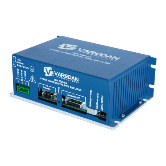
This manual describes the operation and installation of the VSA series PWM servo amplifiers manufactured by Varedan Technologies. This is the section most people skip over, but it does have some useful information, so please take the time to read it. - Page 6 VSA Series Product User Guide 1.1 Main Parts 1.1.1 Module Parts USB/RS232Connection DSP Program Switch Status LED Signal Connector Reset Switch Feedback Connector DC Bus Connector Motor Connector Baseplate Page 6...
- Page 7 VSA Series Product User Guide 1.1.2 Stand Alone Parts USB/RS232Connection DSP Program Switch Status LED Signal Connector Reset Switch Feedback Connector Motor Connector Baseplate AC Power Input Page 7...
-
Page 8: Model Part Numbering
VSA Series Product User Guide 2 Model Part Numbering The following table illustrates the various part numbers used to define the available model configurations. 2.1 Modules VSA - 1530 - 170 - 1 - 1 Varedan switching amplifier Continuous Power Peak Power Maximum DC Bus Voltage Hardware Configuration Code... -
Page 9: Safety Information
VSA Series Product User Guide 3 Safety Information You REALLY need to read this information before operating this amplifier. 3.1 Hazardous Voltage Information CAUTION Hazardous voltages are present at the motor output terminals, input power connection, and within the sheet metal enclosure. Disconnect the power before plugging / unplugging any connections or before servicing or disassembling the enclosure. -
Page 10: Module Specifications
VSA Series Product User Guide 4 Module Specifications 4.1 Mechanical & Environmental Size 7.125 X 4.60 X 1.45 inches Weight 0.94 lb (0.43 kg) Ambient temperature 0 to +45 ° C operating, -40 to +85 ° C storage Humidity 0% to 95%, non-condensing Contaminants Pollution degree 2 Environment... -
Page 11: Stand Alone Specifications
VSA Series Product User Guide 5 Stand Alone Specifications 5.1 Mechanical & Environmental Size 7.125 in X 4.60 in X 2.50 inches Weight 0.94 lb (0.43 kg) Ambient temperature 0 to +45 ° C operating, -40 to +85 ° C storage Humidity 0% to 95%, non-condensing Contaminants... -
Page 12: Electrical Specifications
VSA Series Product User Guide 6 Electrical Specifications Module Stand Alone MODEL VSA-1530 VSA-2050 VSA-1530-SA VSA-2050-SA Input Voltage 70-340 VDC 70-340 VDC 80-240 VAC Single-Phase Motor bus = AC Input Volts * 1.414 Output Power Peak Current Amps Peak time Seconds Continuous current Amps... -
Page 13: I/O Interface Drawings
VSA Series Product User Guide 6.1 I/O Interface Drawings 6.1.1 Digital Inputs The following drawing shows the circuitry for Enable, Reset, Fault and the User I/O pins when configured as inputs. Fault, Enable, Reset, User1,2,3,4 Configured As Inputs Input Voltage Range 0-5 VDC Internal Pull-up 4.7k ohms... -
Page 14: Regen Output
VSA Series Product User Guide 6.1.4 Regen Output The following drawing shows the circuitry for Regen output. This output can be used to control an external relay when the bus voltage exceeds a preset level. The relay should have a dumping resistor connected in a manner that will safely handle the extra voltage. -
Page 15: Encoder Inputs And Outputs
VSA Series Product User Guide 6.1.7 Encoder Inputs and Outputs The following drawing shows the typical encoder input circuit. Jumper JP3 controls the encoder load. With the jumpers all in, 100-ohm resistors are place across the encoder inputs as shown. When Encoder Type is set to “S”... - Page 16 VSA Series Product User Guide 6.2 Stand Alone AC Input Power Wiring The following drawing shows the recommended connection for the AC input to the stand alone package. Connect the AC mains and earth ground to the appropriate pins on the mating connector and double check the wiring before plugging the mate into the amplifier.
- Page 17 VSA Series Product User Guide 6.3 Stand Alone Motor Wiring 6.3.1 Three-Phase Motor Wiring Brushless Servo Motor Case Ground 6.4 Single-Phase Brush Motor Wiring Brush Servo Motor Case Ground Page 17...
- Page 18 VSA Series Product User Guide 6.5 Module Motor and Bus Connections 6.5.1 Three-Phase Motor and Bus Connections Supply Brushless Servo Motor Case Ground 6.5.2 Single-Phase Motor and Bus Connections Supply Brush Servo Motor Case Ground Page 18...
-
Page 19: Connector Descriptions
VSA Series Product User Guide 7 Connector Descriptions 7.1 Main Signal Connector There are 2 different connector options for the main signal connector, a 15-pin Molex or a high density DB-26. The 15-pin Molex is typically used for 2-phase external current mode configurations. The signals for each connector are shown below. -
Page 20: J1 Main Signal Connector (-1 And -3 Models)
VSA Series Product User Guide Pin 9 7.1.2 J1 Main Signal Connector DB-26HD Pin 1 Type: DB-26HD Female Pin 10 Pin 18 Typical Mate Norcomp: 180-M26-103L031 Digikey: 180-M2631MN-ND Pin 26 Pin 19 Signal Name Description Earth Ground Provides electrical connection to the chassis and heatsink of the amplifier DAC A- Input +/-10 VDC analog command input used for analog velocity, analog torque, or 2-phase sine input mode... -
Page 21: J2 Motor Feedback Connector (-1 And -3 Models Only)
VSA Series Product User Guide 7.2 J2 Motor Feedback Connector Pin 5 Pin 1 Type: DB-15HD Female Pin 6 Pin 10 Typical Mate Norcomp: 180-M15-103L031 Digikey: 180-M1531MN-ND Pin 11 Pin 15 Signal Name Description Earth Ground Provides electrical connection to the chassis and heatsink of the amplifier +5VDC Output Provides encoder power, max 200mA. -
Page 22: Motor And Power Connectors
VSA Series Product User Guide 7.3 Motor and Power Connectors The motor and power connections for the module can be one of three types; plug-in, screw terminal or spring clamp, as shown below. The stand alone uses separate connectors for the motor and power connections as shown in sections 7.3.2 and 7.3.3. -
Page 23: Ac Power Connector For Stand Alone Model (Rear Of Stand Alone Case)
VSA Series Product User Guide 7.3.3 AC Power Connector For Stand Alone Model (Rear of Stand Alone Case) Note pin orientation compared to Motor Connector Type: On Shore Technology EDSTLZ960/3 Typical Mate On Shore Technology: EDZ960/3 Digikey: ED1734-ND Pin 1 Signal Name Description Line... -
Page 24: Amplifier Input Power Requirements
VSA Series Product User Guide 8 Amplifier Input Power Requirements 8.1 Module DC Input Power The VSA amplifier module requires a single DC input voltage in the range of 70-340 VDC (motor bus voltage) connected to the B+ and B- inputs. All internal voltages are derived from this DC input voltage. Note that B+ and B- are internally isolated. -
Page 25: User Intefaces
VSA Series Product User Guide 9 User Intefaces 9.1 Serial Interface The VSA amplifier communicates with a host via a RS232 or USB connection at 115,200 baud. Any “dumb terminal” serial communications program such as HyperTerminal can be used for communications. -
Page 26: Communication Format
VSA Series Product User Guide 9.1.3 Communication Format Once the host communication program is properly configured and the host cable is connected, apply power to the VSA amplifier. The VSA amplifier should respond with the sign-on message which should look like the following text in the terminal window. When the amplifier is ready to accept a new command, the user prompt character “>”... -
Page 27: Pusbutton Switch S1
VSA Series Product User Guide 9.2 Pusbutton Switch S1 The pushbutton switch on the front panel (between the Encoder connector and Amplifier I/O connector) is used to reset the amplifier. A quick press and release of the button should result in a full system reset. As the amplifier comes out of reset (or power on), the 7-segment LED display will flash an “8”... -
Page 28: Status Led
VSA Series Product User Guide 9.4 Status LED The 7-segment LED display on the front panel shows the status of the amplifier in real-time. The amplifier should display an “8” and then a “C” when first powered or after a reset in the disabled state with no errors. -
Page 29: Protection Functions
VSA Series Product User Guide 10 Protection Functions The amplifier has a number of built-in protective functions that disable the amplifier in the event of a sensed fault. The fault conditions are explained in the following sections. 10.1 I T Over Current Protection This function protects the amplifier and motor in the event of an over current condition. -
Page 30: Internal Protection
VSA Series Product User Guide 10.2 Internal Protection The amplifier has multiple internal protective functions that check for error conditions. If an error is found, the amplifier is disabled and the appropriate error code(s) is displayed on the 7-segment LED and reported over the serial interface. -
Page 31: Modes Of Operation
VSA Series Product User Guide 11 Modes of Operation This amplifier is basically a device that outputs and controls current (torque in the motor) to its motor phase connections in either a single-phase or three-phase configuration. How that current gets commanded and where the command comes from is determined by the amplifier’s mode of operation. -
Page 32: Single-Phase Or Brush Motor Torque Mode
VSA Series Product User Guide 11.1 Single-Phase or Brush Motor Torque Mode In this mode the output current is proportional to the applied +/-10 VDC analog voltage or serial command current. The amplifier controls the current in phase A with the positive current command value and the current in phase B with the inverse or negative current command value. -
Page 33: Single-Phase Veolcity Mode
VSA Series Product User Guide 11.2 Single-Phase Veolcity Mode In this mode, the amplifier uses either a motor mounted encoder or a tachometer to provide speed control of the motor. The motor speed is controlled by the amplifier’s PID velocity loop, which in turn provides the current (torque) command to the current loops. -
Page 34: 2-Phase Sine Mode (External Sine Commutation)
VSA Series Product User Guide 11.3 2-Phase Sine Mode (External Sine Commutation) In this mode, an external motion controller provides commutation and supplies two current commands (sine waves 120 degrees apart) to the DAC A and DAC B inputs. The amplifier internally generates the current command for the third phase from the negative sum of the supplied phases C = -(A + B). -
Page 35: Three-Phase Torque Mode
VSA Series Product User Guide 11.4 Three-Phase Torque Mode In this mode, the amplifier uses the motor’s encoder to provide commutation. The current in the motor is controlled by the amplifier’s PI current loops and is proportional to the current (torque) command. The torque command can come from either the DAC A analog input in the form of a +/-10 VDC command voltage, where +10v is full scale (peak) positive current or from the OL=x command from the serial interface (x can be any number between 0.00 and 10.00 representing an equivalent input voltage). -
Page 36: Three-Phase Veolcity Mode
VSA Series Product User Guide 11.5 Three-Phase Veolcity Mode In this mode, the amplifier uses the motor’s encoder to provide commutation and speed control. The motor speed is controlled by the amplifier’s PID velocity loop, which in turn provides the current (torque) command to the current loops. -
Page 37: Three-Phase Position Mode
VSA Series Product User Guide 11.6 Three-Phase Position Mode In this mode, the amplifier uses the motor’s encoder to provide commutation and position control. The motor position is controlled by the amplifier’s position PID loop, which in turn provides the velocity command and current (torque) commands to the internal loops. -
Page 38: Three-Phase Commutation Phase Finding
VSA Series Product User Guide 11.7 Three-Phase Commutation Phase Finding For three phase modes (torque, velocity and position), the motor will perform an initial phase finding when first enabled. The type of algorithm used for the phase finding is determined by the TYPE=n command. When n is set to 6, the amplifier uses the motor mounted halls to determine the initial phasing for the motor, and then switches over to full sine commutation after the first hall transition. -
Page 39: Command List
VSA Series Product User Guide 12 Command List The following commands can be entered over the serial interface and are not case sensitive. When a string of n’s (nnnnn) are shown the data is an integer value. When a string of f’s (ffff) are shown the data is a floating point value. - Page 40 VSA Series Product User Guide CCLIMIT:nn Sets the allowable continuous motor current. Range is 0 to continuous rated current, depending on model. When the sensed motor current exceeds this setting, the over current protection algorithm begins timing for a trip. Sets the commanded spindle direction to Counter-Clockwise.
- Page 41 VSA Series Product User Guide DEFAULTS Do not use this command unless instructed to do so by the factory. Important calibration values are cleared by this command. Sets the factory defaults for all parameters as shown below. Note that the Ampmode is set to 2-phase sine after executing this command.
- Page 42 VSA Series Product User Guide DIR? Returns the actual motor direction as “CW” or “CCW”. Disables the amplifier (kills motor power). No deceleration is performed. DISABLE Same as DIS. DISFAULTS:nnnn Creates a bit mask for maskable faults within the amplifier. See DISFAULTS? for the bit definitions.
- Page 43 VSA Series Product User Guide ENCODERTYPE:n Set the encoder electrical type as either “S” for single ended, or “D” for differential. EXTENABLE:n Configures the amplifier to use the external enable input. Setting this value to “1” enables the external enable input as the enable source. A setting of “0” disables the external input as the enable source.
- Page 44 VSA Series Product User Guide INPUTS? Returns a binary word that is bit encoded with the state of the inputs. bit 0 = Fault (LSB) bit 1 = Enable bit 2 = Ext. Reset bit 3 = User1 bit 4 = User2 bit 5 = User3 bit 6 = User4 bit 7 = Reserved...
- Page 45 VSA Series Product User Guide OVERSPEED:nnnnn Sets the speed in RPM for an overspeed fault condition. Range is 1 to 50000. PKLIMIT:nnn Sets the allowable peak motor current in amps for the I2T protection. Range is 0 to peak rated current, depending on model. PKTIME:f.ff Sets the time out value for the I2T protection.
- Page 46 VSA Series Product User Guide STOP If running, the amplifier decelerates the motor to 0 RPM. STOPHOLD If running, the amplifier decelerates the motor to 0 RPM and goes into Positioning Mode. See the GOTO command. STOPS:nnnnn Sets the stop speed in RPM. Range is 1 to the TOPSPEED setting. SVENABLE:n Sets the modulation mode, either Space Vector (Field Oriented Control) or Pure Sine wave mode.
-
Page 47: Appendix A - Sending And Receiving Setup Files
VSA Series Product User Guide 13 Appendix A – Sending and Receiving Setup Files 13.1 Capturing Settings The current settings can be captured to a file then loaded into another unit or saved and downloaded for future reference. 1. Configure the amplifier with the desired settings to capture. 2. -
Page 48: Edit The Captured Settings
VSA Series Product User Guide 13.3 Edit the Captured Settings 1. Navigate to the file specified in step 4 above. 2. Open the file using a text editor. WordPad is recommended. 3. The first few lines of the file should look similar to the following: DUMPALL >Speed:1100 >... -
Page 49: Appendix B - Firmware Updates
In this mode the normal serial interface is disabled and a special programming interface is activated. Please contact the factory for more detailed programming instructions. 15 Sales and Service Varedan Technologies 3870 Del Amo Blvd Suite 503 Torrance, CA 90503 1-310-542-2320 www.varedan.com...
Need help?
Do you have a question about the VSA-1530-1 and is the answer not in the manual?
Questions and answers