Advertisement
GENERAL DESCRIPTION
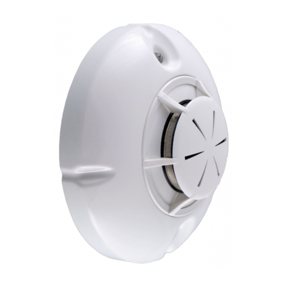
FD7130 addressable optical smoke detector is designed provide early warning of a fire condition by
reacting upon a fixed smoke concentration level in the protected area.
The principle of functioning is based upon smoke particles entering the optical chamber causing
distraction of infrared rays within the chamber. The activation specific smoke concentration level (low,
middle and high) is programmable via Fire Control Panel IFS 7002 through a specialized
communication protocol UniTALK.
A built-in short circuit isolator is available.
The circuit board and the optic chamber (Fig.1, position 4) are mounted within the plastic body (Fig.1,
position 5). Two LEDs, (Fig.1, position 3), offering 360° visibility, illuminate to indicate the following:
-Duty Mode - both LEDs flash repeatedly every 16 seconds.
-Fire condition - both LEDs illuminate constantly.
-Activated isolator - both LEDs flash repeatedly with 1Hz frequency .
-Short circuit at the remote indicator output - both LEDs flash repeatedly with 2Hz frequency.
-Necessary service-both LEDs flash repeatedly with 2Hz frequency.
TECHNICAL DATA
Supply voltage U
L
Current consumption in quiescent state
Alarm state current
Sensitivity
Protected area
Installation height
Degree of protection
Operational temperature range
Relative humidity resistance
Dimensions (incl. base)
Weight (incl. base)
Wires
Cross section of the wires
INSTALLATION
The fire detector type FD7130 operates with bases type 7100. To install the fire detector and its base
follow the sequence:
1. Fix the base on the ceiling of the protected premises using appropriate fixings.
2. Complete the wiring as shown on fig. 2 and in accordance with the construction projects of the site.
3. Replace the detector head on the base and rotate it in a clockwise direction to reach the base's
leading channels (Fig.1, position 2). Continue rotating in a clockwise direction to complete location
(Fig.3.1). The bench marks of the head and the base should fully coincide (Fig. 3.2).
4. To lock the detector head to the base separate the key from the base (Fig. 4, position 3) and keep it
in a safe place, cut the technological edge (Fig. 4, position 1) of the click (Fig. 4, position 2) and
complete the instructions described above.
5. To unlock the detector head insert the key into the slot, according to Fig.4, rotate the fire detector
anticlockwise until rest, take the key out and continue rotating to release the head.
ТTESTING THE FIRE DETECTOR
Test the fire detector after installation, as a part of the site's fire alarm system or after maintenance, in
accordance with the requirements set in section Service schedule.
To test the fire detector follow the sequence:
1. Apply power to the fire detector from the fire alarm control panel IFS 7002 via the fire alarm loop.
2. Wait until the fire detector is set to Duty Mode and exert influence on the fire detector by smoke
generator or another device with aerosol simulator of smoke. Within 40 seconds the fire detector shall
enter fire condition and the LEDs (Fig.1, position 3) shall illuminate continuously.
3. Send a reset command from the fire control panel to the fire detector under testing. The fire
detector shall restore the Duty Mode.
SERVICE SCHEDULE
1. Inspection for visible physical damage
2. Satisfactory operation test in real conditions
3. Check and clean dust contamination
4. Check and clean base and head contacts and connections
To complete task 3 remove the head(Fig.1, position 6) and the chamber's upper part (Fig.1, position 7).
Clean using a small brush. The chamber's upper part can be detergent washed, rinsed and dried.
ATTENTION: When locating the optical chamber fix the upper part so that bench marks coincide.
WARRANTY
The warrant period is 36 months from the date of purchase. The manufacturer guarantees the normal
operation of the unit providing that the requirements set herein have been observed. The manufacturer
does not bear warranty liabilities for damages caused through accidental mechanical damage, misuse,
adaptation or modification after production. The manufacturer bears warranty liabilities for damages in
the fire detector caused through manufacturer's fault only.
Manufacturer: UniPOS Ltd., 114 Grenaderska Street, Pleven 5800, Bulgaria, http://www.unipos-bg.com
ADDRESSABLE OPTICAL SMOKE
DETECTOR
TYPE
INSTRUCTION MANUAL 01-7130-11-05
FD 7130
(15-30)V DC
< 310µA
(2 ± 1) mA
in accordance with EN 54-7:2000
circle with diameter 15m
up to 16 m
IP 43
minus 10°C / plus 60°C
(93 ± 3) % at 40°C
Ø 100 mm, h 47 mm
0,100 kg
two-wire, shielded
2
up to 2.5 mm
- weekly
- monthly
- every 6 months
- Annually
051-5
1293
Advertisement
Table of Contents

Subscribe to Our Youtube Channel
Related Manuals for UniPOS FD 7130


Summary of Contents for UniPOS FD 7130
- Page 1 The manufacturer bears warranty liabilities for damages in the fire detector caused through manufacturer's fault only. Manufacturer: UniPOS Ltd., 114 Grenaderska Street, Pleven 5800, Bulgaria, http://www.unipos-bg.com...
- Page 2 Fig.1 +OUT +OUT FD7130 FD7130 -IN/OUT -IN/OUT RI/KL RI/KL IFS7002 RI31 / RI31S Fig.2 Fig.3.1 Fig.3.2 Fig.4 Manufacturer: UniPOS Ltd., 114 Grenaderska Street, Pleven 5800, Bulgaria, http://www.unipos-bg.com...
Need help?
Do you have a question about the FD 7130 and is the answer not in the manual?
Questions and answers