Table of Contents
Advertisement
Quick Links
Be sure to read this manual before use.
Store this manual with care so that you can refer to it whenever necessary.
- CONTENTS -
............................................... 3
1.1 WARNING SIGN ...................................... 3
1.2 SAFETY CONCERNS ............................... 3
1.3 SAFETY VALVE ....................................... 5
.................................... 9
5.1 FRAME HEAD AND JAW CASE UNIT ............10
5.2 SPOOL UNIT ..........................................11
5.3 CYLINDER UNIT ......................................12
5.4 CHECKING HYDRAULIC OIL ......................13
5.5 NOZZLE UNIT .........................................15
.................................17
7.1 HEAD AREA ...........................................17
7.2 SWIVEL UNIT AND BOOSTER UNIT .............19
..... 6
.............. 7
..........10
...........................16
...........20
1
Advertisement
Table of Contents

Related Manuals for Lobtex ARV-022M

Summary of Contents for Lobtex ARV-022M
-
Page 1: Table Of Contents
- CONTENTS - 1. SAFETY ..........3 1.1 WARNING SIGN ........3 1.2 SAFETY CONCERNS ....... 3 1.3 SAFETY VALVE ........5 2. NAME AND SPECIFICATION OF EACH PART ..6 3. PREPARATION BEFORE USE ....7 4. HOW TO RIVET ........ - Page 2 • It is user’s responsibility to understand the contents of this manual thoroughly. • Lobtex Co., Ltd. has the copyright of this manual. It is prohibited to publish, copy or translate to other language without prior consent.
-
Page 3: Safety
1. 1. 1. 1. Safety SAFETY Followings are safety items to handle this tool. WARNING SIGN This manual includes warning signs shown below to protect users from possible injuries or damages to properties. There are different signs depending on the level of potential damage in case of negligence. - Page 4 Use the tool with bad physical condition may cause accidents or injury. ■ If you need repair, consult with the store you purchased this tool or Lobtex Co, Ltd. Repairing with lack of knowledge or technique may not be able to fix the tool properly and...
-
Page 5: Safety Valve
Safety valve must not be removed or disassembled. Safety valve is an especially important safety device. If it is accidentally loosened or damaged, consult with the store you purchased the tool or Lobtex Co, Ltd. • Do not use the tool without resetting safety valve after it blows off. -
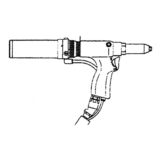
Page 6: Name And Specification Of Each Part
Jaw Pusher Swivel Joint Jaw Case Head Booster L-type Quick Joint Branch Plug Safety Valve Cylinder Air Cylinder Cap Silencer SPECIFICATION Model Number ARV-022M Weight Head 1.3kg Total 5.0kg Working Air Pressure 0.49-0.59Mpa(5.0-6.0kgf/cm Air Consumption 100liters/min Tool Stroke 19mm Traction Power at 0.49MPa(5kgf/cm... -
Page 7: Preparation Before Use
3. Preparation Before Use PREPARATION BEFORE USE The tool must be prepared by the following procedure: (1) Set up a correct nosepiece and a correct guide pipe according to the size of rivet to be used. Default setup is 3.2 mm-diameter nosepiece and yellow guide pipe. - Page 8 3. Preparation Before Use (3) Prepare an air compressor. Be sure to place an air filter and an air regulator between the compressor and the air riveter. Complete Air Supply System Air Filter Air Compressor Pressure Regulator (4) Set up 0.49 to 0.59 Mpa (5 to 6 kgf/cm ) as air pressure.
-
Page 9: How To Rivet
4. How to Rivet HOW TO RIVET Following is the procedure for riveting: (1) Drill a prepared hole (0.1 to 0.2mm larger than the flange diameter of the rivet) in the material to be riveted. Switch Ring (2) Turn the switch ring of vacuum device to ON to Condition of Vacuum Activated activate the device. -
Page 10: Cleaning And Maintenance
5. Cleaning and Maintenance CLEANING AND MAINTENANCE Riveting for a long time generates chips and dust at several parts, which causes troubles. The tool needs periodical cleaning and maintenance according to this manual. Before cleaning and maintenance of each part, make sure that the power of air compressor is turned off to stop air supply and eliminate the residual pressure. -
Page 11: Spool Unit
5. Cleaning and Maintenance (3) Pull Collar to the direction shown in the Whirl-stop Ring Jaw Case Head figure to loosen jaw case head and remove it. (4) Remove jaw pressure spring, guide pipe, jaw Jaw Pusher Spring Jaw Case Lock Nut pressure and jaw. -
Page 12: Cylinder Unit
5. Cleaning and Maintenance (3) Push up the spool with a plastic stick that does not hurt it, and remove the spool. Plastic Stick Spool ● Cleaning (4) Clean up each part with a brush. In this case, make sure that the small hole of the spool is not plugged. -
Page 13: Checking Hydraulic Oil
5. Cleaning and Maintenance ● Assembly (5) Assemble parts in reverse procedure of disassembly. When assembly, apply lubricant oil on the O-ring of the air piston. CHECKING HYDRAULIC OIL Generally, riveting is completed by only one trigger operation. However, if hydraulic oil is decreased, multiple trigger operations are needed. -
Page 14: Disconnecting Hydraulic Coupler
5. Cleaning and Maintenance Make sure to use Lobtex’s hydraulic oil. Other manufacturer’s oil may affect the tool’s performance negatively. (6) Press the tank lightly not to allow air to go into the tank and replace the cap and the oil tank cap. -
Page 15: Nozzle Unit
5. Cleaning and Maintenance NOZZLE UNIT If dust is accumulated at nozzle unit, power of vacuuming rivet’s shaft weakens. If power of vacuuming shaft is getting weak, check as following procedure: ● Disassembly (1) Stop air supply. (2) Remove the tank unit or the chute hose. Tank Unit (3) Remove the nozzle unit from the main unit by Nozzle Unit... -
Page 16: Troubleshooting
6. Troubleshooting TROUBLESHOOTING When any breakage is suspected, try following procedures. If the following procedures cannot solve the problem, consult with Lobtex or ask repair. Malfunction Possible cause Countermeasures Rivets cannot be 1. Nosepiece is wrongly used. 1. Use proper Nosepiece with the rivet inserted, or shafts cannot size. -
Page 17: Part Drawings
7. Part Drawings PART DRAWINGS HEAD AREA Head Unit is consisted of the following parts:... - Page 18 7. Part Drawing Part Name Part Part Name Part No. Nosepiece 3.2 10028 Oil Piston 23627 Frame Head 10105 Urethane O-ring P-22 25443 Jaw Case Head 10280 B-ring P-22 10181 Jaw (Hard tool material, 10281 Returning Spring 23632 Medium) Jaw Pusher 10132 O-ring S-24 10185...
-
Page 19: Swivel Unit And Booster Unit
7. Part Drawing 7.2 SWIVEL UNIT AND BOOSTER UNIT Swivel unit and booster unit are consisted of the following parts:... - Page 20 7. Part Drawing Part Name Part Part Name Part No. O-ring P-11 23663 Oil Cylinder Joint 23700 O Swivel Joint 23662 Button Bolt with Hexagon Hole 23701 M6×20 O-ring S-14 10152 Returning Spring 23691 O-ring P-10A(Cut) 23738 Air Cylinder 23706 O-ring P-14 10434 Straight Joint...
-
Page 21: Storage/Ordering Parts
ORDERING PARTS Clearly identify the model No, part No, and quantity in the order sheet, and submit it to the store you purchased this tool or directly to Lobtex local sales office. (You may refer “7 Part drawing.”) Model No. - Page 22 LOBTEX Home Page OsakaNishi Mazda ldg. 8th FL. 3-25, Sakuragawa 1-Chome, Naniwa-kU, Osaka 556, Japan TEL(0729)80-1111 FAX(0729)80-1166 AUG.2003...
Need help?
Do you have a question about the ARV-022M and is the answer not in the manual?
Questions and answers