Table of Contents
Advertisement
Quick Links
Advertisement
Table of Contents

Related Manuals for Daewoo FRS-T20BA Series


Summary of Contents for Daewoo FRS-T20BA Series
- Page 1 FRST20BA00...
-
Page 2: Table Of Contents
TABLE OF CONTENTS 1. EXTERNAL VIEWS ---------------------------------------- 1-1. EXTERNAL SIZE ---------------------------------------- 1-2. NAME OF PARTS ---------------------------------------- 2. SPECIFICATIONS ---------------------------------------- 2-1. OUTLINE ---------------------------------------- 2-2. ELECTRIC PARTS ---------------------------------------- 2-3. POWER CORD ---------------------------------------- 2-4. DOOR COLOR ---------------------------------------- 3. OPERATIONS AND FUNCTIONS ---------------------------------------- 1. DISPLAY ---------------------------------------- 2. -
Page 3: External Views
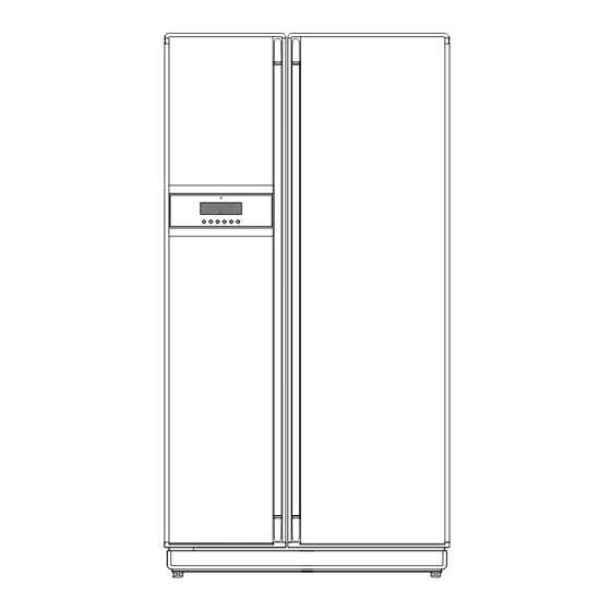
1. EXTERNAL VIEWS 1-1. EXTERNAL SIZE - - 3 -... - Page 4 - - 4 -...
- Page 5 - - 5 -...
- Page 6 - - 6 -...
-
Page 7: Name Of Parts
1-2. NAME OF PARTS Freezer Compartment Refrigerator Compartment 1. Freezer Light 9. Deodorizer 2. Freezer Pockets 10. Dairy Pocket 3. Freezer Shelves 11. Refrigerator Top Light 4. Freezer Pocket Guide 12. Refrigerator Small Pocket 13. Wine Holder 5. Ice Cubes Maker 6. - Page 8 Freezer Compartment Refrigerator Compartment 1. Freezer Light 9. Deodorizer 2. Freezer Pockets 10. Diary Pocket 3. Freezer Shelves 11. Refrigerator Top Light 4. Freezer Pocket Guied 12. Refrigerator Small Pocket 5. Ice Cubes Maker 13. Wine Holder 6. Ice Cubes Case 14.
-
Page 9: Specifications
2. SPECIFICATIONS 2-1. OUTLINE DIVISION CONTENTS MODEL NAME FREEZER ISO Gross Volume(L) REFRIGERATOR TOTAL FREEZER ISO Storage Volume(L) REFRIGERATOR TOTAL WIDTH EXTERNAL DEPTH DIMENSION (mm) 1808 1808 HEIGHT 150g /190g(Europe) REFRIGENT R134a COOLING SYSTEM Fan Cooling System COOLING & CONTROL Fin Evaporator Forced DEFROST SYSTEM SYSTEM... -
Page 10: Electric Parts
2-2 ELECTRIC PARTS 1) COMPRESSOR REFRIGERANT R134a 230 /50 VOLTAGE ( V/HZ) 100 /50,60 110 / 60 115,120/60 127/60 220 / 60 220 ~240/50 (EUROP) COMP MODEL HBL27YG-3 HCL27YG-2 HPL27YG-4A HPL30YG-5 DK190Q-L2U PART CODE 3952127R30 3957127R20 3956127R40 395S130R50 3956190D50 STARTING TYPE CSIR RSCR RSCR... - Page 11 5) F-FAN MOTOR REFRIGERANT R134a VOLTAGE ( V/HZ) 100 /50,60 110 / 60 115,120/60 127/60 220/60 220~240 / 50 230 / 50 TYPE NAME BL-2213DWFA-1 PART CODE 3015911300 REVOLUTION DC 12V 2200RPM 6) R-FAN MOTOR REFRIGERANT R134a VOLTAGE ( V/HZ) 100 /50,60 110 / 60 115,120/60...
- Page 12 10) LAMP ASSEMBLY REFRIGERANT R134a VOLTAGE ( V/HZ) 100 /50,60 110 / 60 115,120/60 127/60 220/60 220~240 / 50 230 / 50 SPEC (W) 120V 15W 240V 15W PART CODE 3013600070 3013600060 SPEC (W) 120V 25W 230~240V 25W PART CODE 3013602020 3013602010 11) MAIN PCB ASSEMBLY...
-
Page 13: Power Cord
2-3. POWER CORD NO SHAPE OF POWER CORD PART CODE DESCRIPTION REMARK 3011315000 CP-2PIN For european country 401RA17200 CP-2PIN For other country 4006D17101 KP-30 For America & El Salvador 401PD17101 KP-211 For Japan & Taiwan 3011300801 BP-3PIN 3011303010 # 267 For Chile 3011315310 For Israel... -
Page 14: Door Color
2-4. Door Color Code 1) Assembly Freezer Door - FRS-T20BA* / FRS-T20HA* / FRS-T24BA* / FRS-T24HA* Blowing Agent Cyclo Pentane Color Type NOBLESS SILVER NEO WHITE LUXURY MIRROR CHERRY WOOD THE OTHERS Color Code NAH4A NHH4G LMH4G CWH4W THE OTHERS 300005434A 300005432A 300005430A... -
Page 15: Operations And Functions
OPERATION AND FUNCTIONS 1. DISPLAY INPUT Control Object Front PCB buttons FRZ SET. button REF SET. button SUPER FRZ. button SUPER REF. button LOCK Button / SLEEP button CONTENTS 1. Normal Operation 1) Temperature control of Freezer / Refrigerator ( Initial mode : Freezer & Refrigerator Middle ) 2) Lock mode / Sleep mode : OFF 3) SPEED icon : inactive 4) FUZZY &... - Page 16 OPERATION AND FUNCTIONS CONTENTS REMARK 2. "FRZ SET." button Temperature control of Freezer compartment 5 steps of sequential temperature mode Initial mode by power input : "MID" (Temperature and bars are shown.) * Letters are not indicated at Soft-Mid and Mid-Strong modes. (Just Setting temperatures and bars are shown.) Temperature progress : Low (Low-Mid)
- Page 17 OPERATION AND FUNCTIONS 2. Temmperature Control of Freezer Compartment (FC) INPUT Control Object 1. FRZ. SET button 1. COMP 2. SUPER FRZ. button 2. F-FAN 3. F-sensor CONTENTS REMARKS 1. Temperature modes change by pushing the button. Mid-High High Low-Mid 2.
- Page 18 OPERATION AND FUNCTIONS CONTENTS REMARKS 6. SUPER FRZ. (Quick Freezing) * ON/OFF DIFF. : 1) Comp. and F-fan are ON (about 150 minutes) regardless of F-sensor. fixed by MICOM 2) F-fan runs at 14V for the first 90 min., then at 12V for the rest time. * STEP DIFF.
- Page 19 OPERATION AND FUNCTIONS CONTENTS REMARKS 6. Control point of each mode Temp Weak refrigeration point (Off point+7 ON point ON/OFF -0.8 DIFF (0.35 deg) OFF point -0.3 -1.3 STEP DIFF STEP DIFF MODE High (Low-Mid) (Mid-High) 7. Super refrigeration proceeds for 40 minutes. Example of temperature change (Refrigerator ;...
- Page 20 OPERATION AND FUNCTIONS 4. SLEEP Mode INPUT Control Object 1. COMP 2. R-FAN 1. SLEEP button 3. F-FAN 4. CUSTOM-LCD CONTENTS REMARKS 1. This mode starts with a push of SLEEP button. 2. Conditions to start Sleep mode F-sensor = -13 Unless it is a restart within 40 minutes after the end of previous Sleep mode F-sensor error Door switch error...
- Page 21 OPERATION AND FUNCTIONS 5. Silence Mode INPUT Control Object 1. COMP 2. R-FAN 1. CDS SENSOR 3. F-FAN 4. CUSTOM-LCD CONTENTS REMARKS 1. Purpose of Silence mode To reduce refrigerator noise at night by decresing fan RPM to a minimum degree 2.
- Page 22 OPERATION AND FUCTIONS CONTENTS REMARKS 1. Fan voltage of each control mode Control Mode F-FAN R-FAN C-FAN Normal Normal Load Control Silence Silence Normal Normal Sleep Mode2 Load control 2. Control against (under) load (Load Control) 1) Purpose : To restore F/R-temperature which has risen by load (much foods in or frequent door openings) as soon as possible 2) Display : "SPEED"...
- Page 23 OPERATION AND FUNCTIONS CONTENTS REMARKS 3. Control Time Chart of Each Mode 1) Start & stop of load control mode (Normal Control) Door On + 5deg F Fan 20min. On + 5deg 20min. R Fan Ref. Load Door Open Frz. Load stop Frz.
- Page 24 OPERATION AND FUNCTIONS CONTENTS REMARKS 4. Flow Chart of Load Control Mode Start Load control is avoided ? F/R door open time is over 30 sec. ? F/S ON + 5deg? Freezer Compartment Overload of both Overload compartments R-sensor ON + 5deg? Refrigerator Compartment Overload...
-
Page 25: Defrosting Mode
OPERATION AND FUNCTIONS 7. Defrosting Mode INPUT Control Object 1. Total comp. work time 2. Comp. work rate 1. Defrosting Mode 3. RT temperature 4. Total door open time CONTENTS Remark 1. Conditions to start defrosting cycle 1) Total comp. work time : 6, 8, ..24 hours. 2) Total door open time : 3 minutes (Any door - F or R - open time is over 3 minutes.) 3) Total time of [comp. - Page 26 OPERATION AND FUNCTIONS CONTENTS REMARKS 3. Flow Chart of Defrosting Start Start Comp. work time is over 2 hours ? Total time is over 60 hours ? Comp. work time is over 24 hours ? Comp. work time is over 6 hours ? Total door open time is over 3 minutes ? Any error ?
-
Page 27: Defrosting Cycle
OPERATION AND FUNCTIONS 8. Defrosting Cycle INPUT Control Object 1. COMP 2. F-FAN 1. Defrosting Cycle 3. R-FAN 4. HEATER CONTENTS REMARKS 1. Defrosting Mode 1) Time ; 50 minutes 2) Comp. / F-fan : ON Pre-Cool R-fan : Control Heater : OFF 3) If F-sensor - 27 , then PRE-COOL becomes OFF... -
Page 28: Error Display
OPERATION AND FUNCTIONS 9. Error Display (LCD Display of Front PCB) INPUT Control Object 1. Temperature Control Buttons CONTENTS REMARKS 1. How to start 1) Press "Lock" button. 2) Push "Lock" button 3 times while pushing " REF SET" button at the same time. 2. - Page 29 OPERATION AND FUNCTIONS CONTENTS REMARKS 6. Control way of Errors (if any ) 1) "F1" ERROR Cause : F-sensor disconnection / short Control : Condition of ambient temperature RT/S ~7 C over 29 Work rate 14/ 50 16 / 41 27 / 45 26 / 22 35 / 20...
-
Page 30: Lcd Back Light
OPERATION AND FUNCTIONS 10. Forced Defrosting INPUT Control Object 1. "FRZ. SET" Button 2. "REF. SET." button Defrosting Mode 3. "LOCK" button CONTENTS REMARKS 1. How to start Set "LOCK ON" first, then push "REF. SET" button 5 times while pushing "FRZ. SET" button simultaneously. 2. - Page 31 OPERATION AND FUCTIONS CONTENTS REMARKS 1. Conditions to turn on LCD Light 1) Power input (plugin) 2) When any button on the panel is pushed, first the back light turns on, then button control is done. 3) When F/R door is open, the light turns on. 2.
- Page 32 OPERATION AND FUNCTIONS 16. Function of Electric Components INPUT Control Object COMP COMP ON/OFF F-FAN CONTENTS REMARKS F-fan delay by comp. ON/OFF F-fan is ON/OFF 1 minute after comp. is ON/OFF. 1 min. 1 min. 2) F an Delay and Priority O N c o n d i t io n R F A N O F F...
-
Page 33: Control Of Interior Lights
OPERATION AND FUNCTIONS 17. Control of Interior Lights INPUT Control Object Refrigerator Door Freezer Door COMP Home-Bar Door (Home Bar Models Only) CONTENTS REMARKS 1) Control of Refrigerator Compartment Lights R lights turn ON/OFF by R-door switch (ON/OFF). 10 minutes after sensing door open, the lights turn off automatically though door close is not sensed. -
Page 34: Summary Of Function
OPERATION AND FUNCTIONS 19. Regulation of R-sensor OFF Point INPUT Control Object J1, J2 on Main PCB Resistance of R-sensor Mid ON/OFF Point CONTENTS REMARKS Regulation of R-sensor OFF point (1.5degree DOWN) In case refrigeration of refrigerator is weak or insufficient, take the following action. R- SENSOR R26 : R-SENSOR standard resistance in normal mode (31.4K ). -
Page 35: Refrigeration Cycle
OPERATION AND FUNCTIONS 21. Refrigeration Cycle... -
Page 36: Cold Air Circulation
OPERATION AND FUNCTIONS 22. Cold Air Circulation... -
Page 37: Diagram
DIAGRAM 4. Wiring DIAGRAM 1) RSCR Type Wiring Diagram... - Page 38 DIAGRAM 2) CSR Type Wiring Diagram...
- Page 39 DIAGRAM 3. CIRCUIT WIRING DIAGRAM 1) Main PCB...
- Page 40 DIAGRAM 2) FRONT PCB DIAGRRAM...
-
Page 41: Installation Guide
5. INSTALLATION GUIDE 1) Installation Preparation Check if the refrigerator can pass a doorway or enter a door first. Dimensions (Including Door Handles) (Width X Depth X Height) 942mm X 803mm X 1808mm [FRS-T20B(H)A*] 942mm X 883mm X 1808mm [FRS-T24B(H)A*] Find a suitable place to install.5 Sufficient space from refrigerator back to the... - Page 42 2) If the refrigerator can not enter the door, follow these steps. Removing Freezer Door Remove front bottom cover first, if it is attached. Unscrew top hinge cover with a screw driver. Insert a thin screw driver into the side groove of the cover to remove.
- Page 43 Removing Refrigerator Door Unscrew top hinge cover with a screw driver. Insert a thin screw driver into the side groove of the cover to remove. Turn top hinge fastener counterclockwise 3~4 times. Disconnect harness wires. Lift up the front of hinge to remove. (After the hinge is removed the door can fall down forward.
- Page 44 Replacing Freezer Door Insert the bottom hole of freezer door straight to the bottom hinge pin. Let the top of door close to the cabinet and insert the top hinge pin to the top hole of freezer door. ( Insert the back of hinge to the groove of protrusion first, then front to the top hole of door.) Turn the hinge fastener tightly to the end.
- Page 45 Replacing Refrigerator Door Insert the bottom hole of refrigerator door straight to the bottom hinge pin. Let the top of door close to the cabinet and insert the top hinge pin to the top hole of freezer door. ( Insert the back of hinge to the groove of protrusion first, then front to the top hole of door.) Turn the hinge fastener tightly to the end.
-
Page 46: Front Cover
3) Refrigerator Leveling & Door Adjustment (If needed.) Refrigerator must be level in order to maintain optimal performance and desirable front appearance. (If the floor beneath the refrigerator is uneven, freezer and refrigerator doors look unbalanced.) In case freezer door is lower than refrigerator door... Insert a screw driver (flat tip) into a groove of the left wheel (bottom of freezer) and turn it clockwise until the door is balanced. - Page 47 6. EXPLODED VIEW 6-1) FRS-T20BA* / FRS-T24BA* CABINET...
- Page 48 EXPLODED VIEW MECH ROOM...
- Page 49 EXPLODED VIEW R-Room...
- Page 50 EXPLODED VIEW F ROOM...
- Page 51 EXPLODED VIEW F-Door...
- Page 52 EXPLODED VIEW R-Door...
- Page 53 5-2) FRS-T20BA* / FRS-T24BA* Parts List Part Number Parts Name Q’ty Description ASSY CAB URT 3012908100 HINGE *T *R AS PO T3.0 3012907400 HINGE *T *L AS PO T3.0 3016031400 SPECIAL SCREW 3011472400 COVER HI *T *R 3011472300 COVER HI *T *L 7112401211 SCREW TAPPING T1 TRS 4 x 12 MFZN...
- Page 54 Part Number Parts Name Q’ty Description 38-1 SWITCH P RELAY AS 38-2 3811402100 COVER RELAY DS3-3NORYL S/S 3011113500 CASE VAPORI PP + CTALC 3013201700 HOSE DRAIN B PE FRB-5350NT 3014413730 PIPE WICON AS 3010102100 ABSORBER C MOTR NR FRB-5350NT 3012004400 FIXTURE C MOTR 3015911500 MOTOR C FAN AS...
- Page 55 Part Number Parts Name Q’ty Description 3011177720 CASE CHILLED AS FRS-T24BA* 3018701800 DEO ANTI AS 3011472900 COVER RETURN DUCT HIPS 3011172020 CASE VEGETB A AS FRS-T20BA* 3011178220 CASE VEGETB A AS FRS-T24BA* 3011473200 COVER VEGETB CASE B FRS-T20BA* 3011485400 COVER VEGETB CASE B FRS-T24BA* 3011172160 CASE VEGETB B AS...
- Page 56 Part Number Parts Name Q’ty Description 7142401611 SCREW TAPPING T2 TRS 4 x 16 MFZN 3010924600 CAP F LUVR HIPS 3011473000 COVER SENSOR 3014559510 PLATE LAMP F SBHG T0.8 3017905200 SOCKET F LAMP AS LAMP F 7121300811 SCREW TAPPING T2S PAN 3X8 MFZN 7112401211 SCREW TAPPING T1 TRS 4 x 12 MFZN...
- Page 57 Part Number Parts Name Q’ty Description 3016040200 SPECIAL SCREW FRAME 4X14 S18C 3012604500 HANDLE INTR DR AS 3012201500 FRAME F DR *O 3016040200 SPECIAL SCREW FRAME 4X14 S18C 3010930300 CAP F INTR DR *T ABS+SPRAY 7142401411 SCREW TAPPING T2 TRS 4X14 MFZN 3010964300 CAP F INTR DR *U AS 7142401411...
- Page 58 Part Number Parts Name Q’ty Description 3010930500 CAP R INTR DR *T ABS+SPRAY 7142401411 SCREW TAPPING T2 TRS 4X14 MFZN 3010964400 CAP R INTR DR *U AS ABS+SPRAY 7142401411 SCREW TAPPING T2 TRS 4X14 MFZN PANEL R DR 3014805200 SENSOR D AS PBN-43 EVA AS FUSE TEMP AS...
- Page 59 6. EXPLODED VIEW 6-3) FRS-T20HA* / FRS-T24HA* CABINET...
- Page 60 EXPLODED VIEW MECH ROOM...
- Page 61 EXPLODED VIEW R-Room...
- Page 62 EXPLODED VIEW F ROOM...
- Page 63 EXPLODED VIEW F-Door...
- Page 64 EXPLODED VIEW R-Door...
- Page 65 5-4) FRS-T20HA* / FRS-T24HA* Parts List Part Number Parts Name Q’ty Description ASSY CAB URT 3012908100 HINGE *T *R AS PO T3.0 3012907400 HINGE *T *L AS PO T3.0 3016031400 SPECIAL SCREW 3011472400 COVER HI *T *R 3011472300 COVER HI *T *L 7112401211 SCREW TAPPING T1 TRS 4 x 12 MFZN...
- Page 66 Part Number Parts Name Q’ty Description 38-1 SWITCH P RELAY AS 38-2 3811402100 COVER RELAY DS3-3NORYL S/S 3011113500 CASE VAPORI PP + CTALC 3013201700 HOSE DRAIN B PE FRB-5350NT 3014413730 PIPE WICON AS 3010102100 ABSORBER C MOTR NR FRB-5350NT 3012004400 FIXTURE C MOTR 3015911500 MOTOR C FAN AS...
- Page 67 Part Number Parts Name Q’ty Description 3011177720 CASE CHILLED AS FRS-T24HA* 3018701800 DEO ANTI AS 3011472900 COVER RETURN DUCT HIPS 3011172020 CASE VEGETB A AS FRS-T20HA* 3011178220 CASE VEGETB A AS FRS-T24HA* 3011473200 COVER VEGETB CASE B FRS-T20HA* 3011485400 COVER VEGETB CASE B FRS-T24HA* 3011172160 CASE VEGETB B AS...
- Page 68 Part Number Parts Name Q’ty Description 7142401611 SCREW TAPPING T2 TRS 4 x 16 MFZN 3010924600 CAP F LUVR HIPS 3011473000 COVER SENSOR 3014559510 PLATE LAMP F SBHG T0.8 3017905200 SOCKET F LAMP AS LAMP F 7121300811 SCREW TAPPING T2S PAN 3X8 MFZN 7112401211 SCREW TAPPING T1 TRS 4 x 12 MFZN...
- Page 69 Part Number Parts Name Q’ty Description 3016040200 SPECIAL SCREW FRAME 4X14 S18C 3012604500 HANDLE INTR DR AS 3012201500 FRAME F DR *O 3016040200 SPECIAL SCREW FRAME 4X14 S18C 3010930300 CAP F INTR DR *T ABS+SPRAY 7142401411 SCREW TAPPING T2 TRS 4X14 MFZN 3010964300 CAP F INTR DR *U AS 7142401411...
- Page 70 Part Number Parts Name Q’ty Description 146-7 3012918200 HINGE HOMEBAR *L AS STS304 146-8 3016030600 SPECIAL SCREW C SUS M5 146-9 3010951500 CAP HOMEBAR ARM PLT *L 146-10 3016030800 SPECIAL SCREW A SUS M5 146-11 3016030600 SPECIAL SCREW C SUS M5 146-12 3014567100 PLATE HOMEBAR ARM *R AS...
Need help?
Do you have a question about the FRS-T20BA Series and is the answer not in the manual?
Questions and answers