Table of Contents
Advertisement
Quick Links
I
O
M
NSTALLATION AND
PERATION
ANUAL
FOR
SKYNODE® S100
TRACKING SYSTEM
/
: S100-001
P
N
Document No.: S100-400
Creation: Jan 24, 2007
Revision: 2.01, Jun 17, 2014
LATITUDE TECHNOLOGIES CORPORATION
101-3375 Whittier Ave
Victoria, BC, Canada, V8Z-3R1
Tel: (250) 475-0203
Fax: (250) 475-0204
Email: info@latitudetech.com
Page 1 of 32
Advertisement
Table of Contents

Subscribe to Our Youtube Channel
Related Manuals for Latitude SkyNode S100

Summary of Contents for Latitude SkyNode S100
- Page 1 SKYNODE® S100 TRACKING SYSTEM : S100-001 Document No.: S100-400 Creation: Jan 24, 2007 Revision: 2.01, Jun 17, 2014 LATITUDE TECHNOLOGIES CORPORATION 101-3375 Whittier Ave Victoria, BC, Canada, V8Z-3R1 Tel: (250) 475-0203 Fax: (250) 475-0204 Email: info@latitudetech.com Page 1 of 32...
- Page 2 Jan 24, 2007 First version IMPORTANT NOTICES Information in this document is subject to change without notice. Latitude Technologies reserves the right to change or improve their products and to make changes in the content of this material without obligation to notify any person or organization of such changes or improvements.
-
Page 3: Limited Warranty
Latitude Technologies Corporation warrants products it manufactures against defects in materials and workmanship for a period of one year from the date of factory sale. During the warranty period, Latitude Technologies Corporation will, at its option, either repair or replace products that prove to be defective. -
Page 4: Table Of Contents
® SkyNode S100 Installation and Operation Manual Table of Contents GENERAL INFORMATION ................6 1.1....................6 NTRODUCTION 1.2................. 6 CRONYMS AND BBREVIATIONS 1.3..................6 QUIPMENT URPOSE 1.4................. 6 QUIPMENT ESCRIPTION 1.5.................. 7 QUIPMENT IMITATIONS 1.6.................. - Page 5 APPENDIX B- INTERCONNECT INTERFACES ............25 APPENDIX C- ENVIRONMENTAL TESTS TABLE ........... 30 List of Figures Figure 1 - SkyNode S100 Tracker ....................6 Figure 2 - S100 Outline Drawing ....................10 Figure 3 - S100 Startup Screen ....................17 Figure 4 - S100 Terminal Menu ....................
-
Page 6: General Information
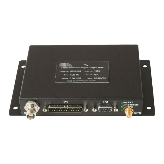
1.1. Introduction The following information refers to the SkyNode S100 Iridium transceiver (henceforth referred to as the “S100”) and tracking controller device; designed and manufactured by Latitude Technologies Corporation. This information is intended solely for reference by End Users, Installers, and Application Developers. -
Page 7: Equipment Limitations
® SkyNode S100 Installation and Operation Manual 1.5. Equipment Limitations Although there is no specific equipment limitation, the installer should refer to the installation recommendations of Section 4 and the Environmental Qualification Table of Appendix C. 1.6. Safety Precautions There is no specific safety precaution as such, associated with this equipment. 2. -
Page 8: Specifications
® SkyNode S100 Installation and Operation Manual 3. SPECIFICATIONS 3.1. Dimensions See Figure 2 below. 3.2. Electrical Specifications Power requirement: +12.0 VDC or +28VDC nominal Input Current: 0.050 A Standby (at 28VDC) 0.160 A Transmit/Receive (Average) 0.500 A Transmit (Peak) 3.3. -
Page 9: Optional Latitude Kits Part Numbers
® SkyNode S100 Installation and Operation Manual 3.6. Optional Latitude Kits Part Numbers The following Optional Part Numbers Kits can be ordered from Latitude Technologies Corp. The KT006 Kit is comprised of the following parts: LATITUDE DESCRIPTION PART NUMBER DB25 Backshell, plastic... -
Page 10: S100 Dimensions
® SkyNode S100 Installation and Operation Manual 3.7. S100 Dimensions Dimensions are provided in inches. Figure 2 - S100 Outline Drawing S100-400, R2.01 Page 10 of 32... -
Page 11: Installation
In case of mismatch, contact Latitude Technologies for details. Perform a visual inspection of the unit to ensure that it was not damaged during shipment. If you ordered the installation kit ensure that all connectors are in the package. -
Page 12: Coax Cables
® SkyNode S100 Installation and Operation Manual 4.3.4. Coax Cables The length of the coaxial cables to both the GPS and Iridium antennas (or combination) is paramount to the performance of the S100 system. Both should be kept to a strict minimum, and this factor should be taken into consideration when planning the installation. -
Page 13: Interfaces
“Weight On/Off Wheels” (when wired to a squat switch), “Engine On/Off” (when connected to the engine hours meter), or many other possibilities. Configuring discrete inputs is done remotely by Latitude Technologies Corporation; for assistance, call +1 (250) 475-0203 and ask for technical support. -
Page 14: Table 5 - S100 Rs-232 Interface
There is an auxiliary RS-232 port available on P1; with select firmware versions, this is can be also be used to output debug data or communicate with Latitude API devices, but not for upgrading firmware. Port settings are the same as for P2. -
Page 15: Antennas
The analog inputs can measure DC voltage levels from ~0V to +28V. You may be required to change the firmware version on your S100 in order to use the analog inputs; call Latitude Technologies at +1 (250) 475-0203 and ask for technical support. 4.4.4. Antennas The following antennas are known to be compatible with the S100. -
Page 16: Table 8 - Gps Antenna Part Numbers
® SkyNode S100 Installation and Operation Manual 4.4.4.2 GPS Antenna Manufacture’s P/N Latitude Description MD019 3G15A2-XT-1 Antcom GPS Antenna 3.5" dia, active LNA 20dB, white Sensor Systems antenna, 3.5” dia, passive GPS antenna, MD24 S67-1575-109 TNC jack, white. Table 8 - GPS Antenna Part Numbers 4.4.4.3... -
Page 17: Operation
® SkyNode S100 Installation and Operation Manual 5. Operation 5.1. Configuration Set-up All S100 units are factory pre-configured to standard default settings. However, should the need arise to modify them, the following steps describe how to use the menu to view and configure the reporting parameters of the S100 device. -
Page 18: Edit Gps Interval
® SkyNode S100 Installation and Operation Manual Figure 4 - S100 Terminal Menu The lower half of the screenshot above shows the options that the S100 Menu provides. Each of the options shown can be accessed by pressing the number or letter to the immediate left of the option (e.g. -
Page 19: View/Reset Message Log
® SkyNode S100 Installation and Operation Manual 5.1.3. View/Reset Message Log The Message Log contains all relevant position messages that have been stored locally. There are two operations that can be performed on the position message log: viewing and clearing. Viewing the messages will display all logged position messages that have not been transmitted successfully. -
Page 20: Post Installation Testing
6.2. Functional Test-No Engine This test requires a facility to monitor the availability of the aircraft on the Latitude web site. Prior to performing this test an account must have been established with Latitude. Communication with the person monitoring the web site is required. -
Page 21: Functional And Emi Test- Engine(S) Running
6.3. Functional and EMI Test- Engine(s) running This test requires a facility to monitor the availability of the aircraft on the Latitude web site. Prior to performing this test an account must have been established with Latitude. Communication with the person monitoring the web site is required. -
Page 22: Troubleshooting
® SkyNode S100 Installation and Operation Manual 7. Troubleshooting 7.1. LED Blink Pattern Description The S100 is equipped with three LEDs (light emitting diodes) located on the front panel, that can be used for visual troubleshooting. The top LED (“SAT”) provides information about the status of the SATCOM link. -
Page 23: Appendix A- Connector Pin Assingments
® SkyNode S100 Installation and Operation Manual APPENDIX A- CONNECTOR PIN ASSINGMENTS P1 (25 pin male D-sub): Name Type Function Range RX AUX RS232 input Auxiliary serial data receive ±15 VDC Ground Signal Ground return 0 VDC TX AUX RS232 output Auxiliary serial data transmit ±5 VDC GPS OUT... -
Page 24: Table 14 - S100 P2 Pin Assignments
® SkyNode S100 Installation and Operation Manual P2 (9 pin female D-sub): Name Type Function Range RS232 output Serial data signal ±5 VDC RS232 output DCE serial data transmit ±5 VDC RS232 input DCE serial data receive ±15 VDC RS232 input Serial data signal ±15 VDC Ground... -
Page 25: Appendix B- Interconnect Interfaces
® SkyNode S100 Installation and Operation Manual APPENDIX B- INTERCONNECT INTERFACES S100-400, R2.01 Page 25 of 32... - Page 26 ® SkyNode S100 Installation and Operation Manual TABLE B1 –WIRING INSTALLATION NOTES ITEM PART NUMBER or EXPLANATION DENOTES COAX CONNECTOR (SMA OR TNC) Single Wires ALL WIRES PER AWG22 UNLESS OTHERWISE SPECIFIED, M22759/41-22-9 OR EQUIVALENT Connector P1 DB25 Connector P2 GPS Antenna M39012/30-0503 (Straight) or M39012/20-0007 (90°) Connector...
- Page 27 ® SkyNode S100 Installation and Operation Manual TABLE B2 –IRIDIUM COAX CABLES CHART Max. Coaxial Cable Min. Matching Connectors Cable Cable Type Bend TNC- male straight TNC- male 90° plug length or supplier (inches Radius plug (P/N) (P/N) (feet) (see below) (inches ≤...
- Page 28 ® SkyNode S100 Installation and Operation Manual TABLE B3 –GPS COAX CABLES CHART Cable length Coaxial Cable Cable OD Min. Bend Matching Connectors (feet) Type (inches) Radius TNC- male straight TNC- male RA plug (inches) plug (P/N) (P/N) M39012/55-4502 M39012/56-4502 MIL-C-17/113 RG316 0.098...
- Page 29 ® SkyNode S100 Installation and Operation Manual Figure B1 – Typical Wiring Installation GPS ANTENNA IRIDIUM ANTENNA COMBINED GPS/IRIDIUM ANTENNA S100-400, R2.01 Page 29 of 32...
-
Page 30: Appendix C- Environmental Tests Table
® Skynode S100 Installation and Operation Manual APPENDIX C- ENVIRONMENTAL TESTS TABLE S100-400, R2.01 Page 30 of 32... - Page 31 ® Skynode S100 Installation and Operation Manual TABLE C1 – ENVIRONMENTAL TESTS TABLE NOMENCLATURE: SKYNODE S100 ______ TYPE/MODEL/PART NO: S100-001 TSO NUMBER: MANUFACTURER’S SPECIFICATION AND/OR OTHER APPLICABLE SPECIFICATION: N/A MANUFACTURER: LATITUDE TECHNOLOGIES CORPORATION ADDRESS: 101-3375 Whittier Ave Victoria, BC, Canada, V8Z-3R1 REVISION &...
-
Page 32: Table 17 - Environmental Qualification Table
® Skynode S100 Installation and Operation Manual Condition Section Description of tests conducted Power Input 16.0 Equipment tested to Category B Tests performed for both 14VDC and 28VDC systems Voltage spike 17.0 Equipment tested to Category B 56Vpk for 10µs Audio Frequency Susceptibility 18.0 Equipment identified as Category X, no test...
Need help?
Do you have a question about the SkyNode S100 and is the answer not in the manual?
Questions and answers