Table of Contents
Advertisement
Advertisement
Table of Contents

Related Manuals for Elstat ems100 nexo


Summary of Contents for Elstat ems100 nexo
- Page 1 ems100 PRODUCT MANUAL Issue 4...
- Page 2 Copyright © Elstat Ltd 2014 All Rights Reserved All information in this document is property of Elstat Ltd Commercial use and distribution of the contents of this publication is not allowed without express and prior written consent of Elstat Ltd...
-
Page 3: Table Of Contents
ems100 Product Manual, Issue 4 CONTENTS 1. CONTROLLER WITH INTELLIGENCE 1.1 Functionality 1.2 User interface 1.3 Overall dimensions 1.4 Mounting 1.5 Electrical connections 1.6 Programming port cover 1.7 Wiring diagram 1.8 Relay ratings 1.9 Temperature input ranges 1.10 Environmental ratings 2. ACCESSORIES 2.1 Temperature sensors 2.2 Door switch 2.3 Motion sensor... -
Page 4: Ems100 Product Manual, Issue
Product Manual, Issue 4 ems100 CONTENTS 4. TROUBLESHOOTING 4.1 ‘Limp home’ functionality 4.2 Door open alarms 4.3 Door alarms ‘Limp home’ mode 4.4 Not cooling problems 4.5 Temperature sensor alarms 4.6 Appliance sensor failure 4.7 Freeze-up protection (888) 4.8 Refrigeration system failure (rSF) alarms 4.9 Condenser high temperature (Ht) alarms 5. PARAMETERS 5.1 Parameters by function... -
Page 5: Controller With Intelligence
The energy management system (ems) controllers from Elstat are used in a variety of drinks coolers, optimising energy savings, without compromising on drinks serving temperature. The ems100 Nexo controller is designed for applications such as single door coolers, double door coolers and vending machines. -
Page 6: User Interface
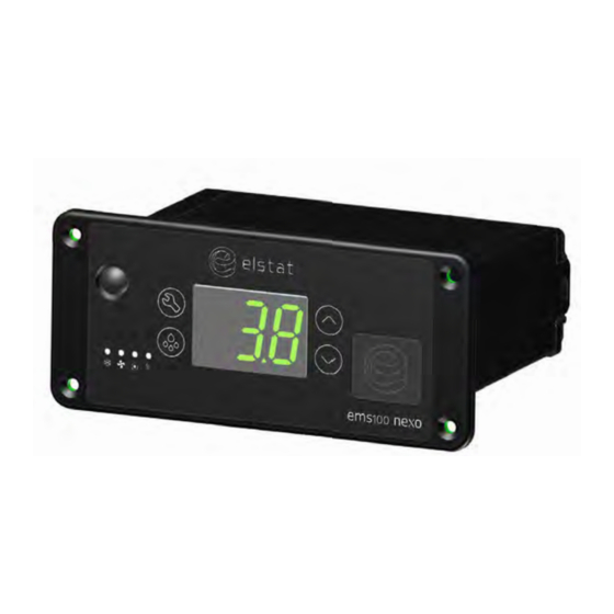
Product Manual, Issue 4 ems100 1.2 User interface All Elstat controllers are made from food grade materials and are safe for internal installation. The ems100 controllers are available with either an integrated or a remote motion sensor. Controller with integrated motion detection... -
Page 7: Overall Dimensions
ems100 Product Manual, Issue 4 Item On display Name Function Motion Sensor Detects motion LED Display Displays the current status of the controller Programmable Port Enables upload of parameters using a dongle 1.3 Overall dimensions The overall dimensions of the controller are shown in the following diagram. 142 mm 103 mm 127.8 mm... -
Page 8: Mounting
Product Manual, Issue 4 ems100 1.4 Mounting 64.2 64.2 - 0.5 - 0.5 ems100 Nexo controllers are 121.3 designed for panel - 0.5 mounting and are secured using four countersunk self- tapping screws. 24.5 - 0.5 41.3 The aperture - 0.5 and screw pitch 24.5... -
Page 9: Electrical Connections
ems100 Product Manual, Issue 4 1.5 Electrical connections Item Description Connectors Compressor Line in Fan(s) Light(s) Product Sensor 12VAC Evaporator Sensor Door Condenser Sensor Appliance Sensor Remote Motion Detector (If applicable) 1.6 Programming port cover When accessing the programming port on the controller fascia, remove the rubber cover and let it hang on the attaching strap. -
Page 10: Wiring Diagram
To remove the potential for damage occurring to, and the potential for failure of, the crimped connection on the mating half of terminals 1 to 4 of the ems100 Nexo controller it is recommended that only right angle insulated 6.3mm tab connectors, complete with strain relief, are used to terminate these cables. -
Page 11: Relay Ratings
122°F to 257°F +/- 10°F Evaporator sensor -15°C to 50°C +/- 0.5°C 5°F to 122°F +/- 1°F Note The NTC (negative temperature coefficient) thermistor from Elstat is rated at: -35°C to 125°C (-31°F to 257°F). 1.10 Environmental ratings Characteristic Value... - Page 12 Product Manual, Issue 4 ems100 Page 12 www.nexo.com...
-
Page 13: Accessories
2. ACCESSORIES 2.1 Temperature sensors Temperature sensors are available from Elstat with various cable lengths. To help identify sensor cables during the installation, Elstat can supply sensor cables with blue identification sleeves. For example, if the appliance sensor cable is plain black; the condenser sensor cable can be purchased with a blue identification sleeve. - Page 14 (Ht) parameter. Ensure that the condenser sensor is fixed using a metal pipe clip (1) or foil tape (2) as shown. Elstat can supply pipe clips for 6-8 mm and 8-10 mm pipes. A - Condenser hot gas pipe (Condenser inlet pipe)
-
Page 15: Door Switch
Door switches are used to detect door openings. They are SELV components that are able to create an open and closed circuit. The Elstat enhanced door switch, and activator, are over-moulded for increased physical protection and resistance to water ingress. - Page 16 60 mm Note Door switches and activators supplied by Elstat must not be installed using rivets. Using rivets invalidates the warranty. The alignment of the door switch and activator is critical for the correct operation of the door switch. The table details alignment tolerances.
-
Page 17: Motion Sensor
ems100 Product Manual, Issue 4 Insert the white wire of the first cable into the connector of the second cable ensuring that the terminal is in the correct orientation. Connect the red wire from the first cable and the white wire from the second cable together using a butt splice or similar. - Page 18 Product Manual, Issue 4 ems100 For a motion sensor that is not mounted flush with the panel, the diagram shows the minimum recommended clearances to ensure motion detection. For example, if the motion sensor is mounted 15mm behind the panel, a 30mm diameter aperture is required. 65 mm ...
-
Page 19: Transformer
Product Manual, Issue 4 2.4 Transformer The ems100 Nexo controller is powered up via the transformer that is available in two options: 120vAC/50-60Hz - 12vAC Transformer 230vAC/50-60Hz - 12vAC Transformer www.nexo.com Page 19... - Page 20 Product Manual, Issue 4 ems100 Page 20 www.nexo.com...
-
Page 21: User Guide
ems100 Product Manual, Issue 4 3. USER GUIDE 3.1 Power-up sequence 8. 8. 8. to confirm that all segments of the display are functioning correctly Platform type and firmware version. (example) Checksum of the parameter set. (example) The display then shows the appropriate display code. For example, the temperature or USE. 3.2 Function buttons The controller buttons access the menus to view parameter values, reset the controller, and to run test routines. -
Page 22: Indicators
Product Manual, Issue 4 ems100 3.3 Indicators Indicator Name Function Colour Compressor On when the compressor is running. Green On when the evaporator fan is running. Green On if the saving temperature is disabled. Saving temperature The controller maintains the Ready mode disable temperatures at all times. -
Page 23: Gdc) Firmware Menus
Clears the self-learning matrix. Resets the parameters settings to the global default values and clears the self-learning matrix and statistics. Full reset Elstat use only. Downloads data from the controller to a computer for analysis. Data dump Elstat use only. -
Page 24: The Menu Arrangement
Selecting Hr - half re-set - will allow a half reset to be performed which will wipe the learning matrix, allowing the controller to re-learn outlet opening and closing times. Note The full reset is to be performed by Elstat personnel. The data dump is for Elstat use only for testing and development purposes. Page 24 www.nexo.com... -
Page 25: Menu Access
Analogue inputs (temperature sensors and door switch) Motion sensor Should a problem be suspected with ems100 Nexo controller it is recommended that the test routine is carried out before disconnecting or replacing the controller. The test routine can detect any loose or disconnected cables and check that the controller is connected properly to the lights, fan and compressor. - Page 26 Product Manual, Issue 4 ems100 3.8.1 Entering the test routine menu Step Action Display Press the Set button The display shows: Enter the appropriate password to access the menu. The display shows: Press the Down button to scroll to the test (tSt) menu The display shows: Press the Set button to enter the test routine Once in the test menu it is possible to select which test to use.
- Page 27 ems100 Product Manual, Issue 4 Follow the routine below for Compressor: Action Button Display Test Check Press Select compressor Compressor relay Compressor is running and Press engaged compressor LED is on Compressor relay Compressor stopped running and Press disengaged compressor LED is off Press Defrost to return to the relay test menu.
- Page 28 Product Manual, Issue 4 ems100 Follow the routine below for Fan: Action Button Display Test Check Press Press Select fan Evaporator fan and the fan LED is Press Fan relay engaged Evaporator fan and the fan LED is Press Fan relay disengaged Press Press Defrost to return to the relay test menu.
- Page 29 ems100 Product Manual, Issue 4 Follow the routine below for All outputs: Action Button Display Test Check Press All outputs Press Select all outputs Press All outputs engaged All outputs are on Press All outputs disengaged All outputs are off Press Press Defrost to return to the relay test menu.
- Page 30 Product Manual, Issue 4 ems100 Then follow the routine: Action Button Display Test Check Appliance sensor input Appliance sensor Displayed temperature is as Press temperature expected Press Press Defrost to return to the analogue input test menu Press Door switch Door is open (dO) or closed (CLO) Press Opening and closing the door should make the display...
- Page 31 ems100 Product Manual, Issue 4 Action Button Display Test Check Press Evaporator sensor input Evaporator sensor Displayed temperature is as Press temperature expected Press Press Defrost to return to the analogue input test menu For future use - Stock sensing Press hardware currently...
-
Page 32: Viewing The Last Three Cooler Faults Witnessed By The Controller (Flt)
Product Manual, Issue 4 ems100 Then follow the routine: Action Button Display Test Check Press Press the Set button to enter the motion sensor test. Place your hand about 300mm from the motion sensor Move your hand from left to right. Check for the following: The display count increments for each detected movement. -
Page 33: Half Reset (Hr)
ems100 Product Manual, Issue 4 Step Action Display The display shows: Press the Down button and scroll to FLt The display shows: Press the Set button to select The last three faults, or alarms, to occur are displayed for example: A condenser high temperature alarm has occurred An appliance sensor alarm has occurred A Condenser Sensor alarm has occurred... - Page 34 Product Manual, Issue 4 ems100 A half reset will not: Adjust, change or alter any of the parameters, or their values, as set by the OEMs or Brands. Fix any issues with cable connection Step Action Display Press the Set button. The displays shows: Enter the button sequence of the main menu entry password...
-
Page 35: Viewing Statistics
ems100 Product Manual, Issue 4 3.11 Viewing statistics Depending on the model, the controllers start gathering a variety of statistics when first powered up. Statistics provide information on the following, dependent on firmware: Activity: Number of motion counts and door openings. Compressor: Number of compressor cycles and total compressor runtime. - Page 36 Product Manual, Issue 4 ems100 Display Statistic Description Total number of motion counts since first powered up or last Motion counts full reset Value of the standby temperature disable PEr parameter. Possible values are: OFF or ON. Saving temperature disable OFF = Saving temperature disable is switched off.
-
Page 37: Troubleshooting
Saving mode. 4.1 ‘Limp home’ functionality As the ems100 Nexo acts as a diagnostic device, and manages various operational functions of the cooler it serves to prevent faults from becoming critical to the cooler, for example over working of the compressor. -
Page 38: Door Alarms 'Limp Home' Mode
The cooler will operate during this period, cooling the products, while a service engineer visit is scheduled. The table below describes how the ems100 Nexo controls the cooler during this time and what the end user will see:... - Page 39 ems100 Product Manual, Issue 4 If in Saving mode and set point is achieved within twenty (20) cycles the controller reverts to normal operation and alternately displays: d0/3Bars. An audio alarm sounds for ten (10) seconds, every ten (10) minutes. If set point is not achieved within twenty (20) cycles the compressor switches off and the controller displays 3BarStack: An audio alarm sounds continuously.
-
Page 40: Not Cooling Problems
Product Manual, Issue 4 ems100 4.4 Not cooling problems Follow the chart below to troubleshoot problems of the cooler not cooling properly leaving the cooler cabinet or product warm. Cooler or product is Check cooler wiring warm and fuses Is power available at the Replace Is controller on? controller main controller connector? Is the Is compressor ... -
Page 41: Temperature Sensor Alarms
The limp home aspect of this alarm ensures that the cooler continues to operate with limited disruption to the end user. The cooler will operate, cooling the products, while a service engineer visit is scheduled. The table below describes how the ems100 Nexo controls the cooler during this time and what the end user will see:... -
Page 42: Freeze-Up Protection (888)
Product Manual, Issue 4 ems100 While the controller displays the above, the controller is managing the compressor and the fans: The compressor cycles fifteen (15) minutes off, then five (5) minutes on. The fan switches on with the compressor on cycle, then cycles when the compressor is in the off cycle as set by the FCO (fan cycle on) and FCF (fan cycle off) parameters. - Page 43 The refrigeration system will operate - cooling the products - while a service engineer visit is scheduled. The table below describes how the ems100 Nexo controls the cooler during this time and what the end user will see:...
-
Page 44: Condenser High Temperature (Ht) Alarms
Product Manual, Issue 4 ems100 4.9 Condenser high temperature (Ht) alarms Condenser high temperature (Ht) alarms alert to problems with the refrigeration system such as a blocked condenser or faulty condenser fan. Follow the chart to troubleshoot condenser high temperature (Ht) alarms. -
Page 45: Parameters
ems100 Product Manual, Issue 4 5. PARAMETERS Operation parameters define the alarms, self-learning, lights management, and also the delay to saving and the saving temperature disable. The parameter values vary between different cooler types, cooler characteristics, operating environments, brand requirements, and operational preferences. Parameter settings are defined by customers and can be loaded and edited automatically, via the XML files, or manually. -
Page 46: Parameter Validation
5.2 Parameter validation The ems100 Nexo controller validates the parameter values that have been manually set by the user by checking that the values do not clash with each other. Below is the set of rules the controller validates the parameter values against: SP must be >... - Page 47 ems100 Product Manual, Issue 4 5.3.2 Differential (dIF) Display Defines the compressor cut-in temperature when added to the set point (SP) Description temperature during the Ready mode. If the differential (dIF) is set too low, for example, less than 2.0°C the compressor may Considerations cycle on the minimum compressor rest time (rt).
- Page 48 Product Manual, Issue 4 ems100 5.3.5 Delay to saving (dS) Display Defines the delay in switching to the Saving mode from Ready mode. Description The delay starts at the end of the last active 30 minute period of the Ready mode. Considerations Set in multiples of 30 minutes.
- Page 49 ems100 Product Manual, Issue 4 5.3.8 Refrigeration system failure (Ct) Display Defines the maximum continuous runtime of the compressor without reaching the set point (SP) temperature. Description If the set point (SP) temperature is not reached within this time, the controller enters the RSF Limp home mode.
- Page 50 Product Manual, Issue 4 ems100 5.3.11 Saving set point (SSP) Display Description Defines the compressor cut-out temperature during the Saving mode. Considerations Must be set above the set point (SP). Range 0.0 to 9.9°C (32 to 50°F) Global default 7.0°C (45°F) 5.3.12 Uninterrupted pull down (IPd) Display Defines the temperature that if exceeded starts an uninterrupted pull down, i.e.
- Page 51 ems100 Product Manual, Issue 4 5.3.14 Defrost interval (dE) Display Defines the period between the end of defrost cycle and beginning of the next defrost Description cycle. A time-based defrost cycle helps improve evaporator efficiency. In the event of power loss, the defrost interval (dE) is not maintained. The defrost interval is reset.
- Page 52 Product Manual, Issue 4 ems100 5.3.17 Fan cycle off (FCF) Display Description Defines the inactive period of the evaporator fan while the compressor is switched off. Considerations Fan cycle is the fan cycle on (FCO) time + the fan cycle off (FCF) time. Range 0 to 30 minutes Global default...
- Page 53 (LO) values are 10% of the actual line in voltages (see table below). • Must not be used with an external voltage stabiliser Considerations • Must only be used with an Elstat supplied transformer Global default 0 (disabled) www.nexo.com...
- Page 54 (HI) values are 10% of the actual line in voltages (see table below). • Must not be used with an external voltage stabiliser Considerations • Must only be used with an Elstat supplied transformer Global default 0 (disabled) 110-120V line...
- Page 55 ems100 Product Manual, Issue 4 5.3.24 Defrost termination temperature (dtd) Display Defines the temperature to end the defrost cycle. Description Ending defrost cycles on temperature minimizes the duration of defrost cycles. • Must be set above the set point (SP) plus differential (dIF) temperature. Considerations •...
- Page 56 Product Manual, Issue 4 ems100 The table below describes the values for activity frequency (AF). Value Name Description Low frequency 1 door opening or 1 motion count Medium frequency 1 door opening or 3 motion counts High frequency 2 door openings or 6 motion counts The controller runs continuously for 48 hours in the ready mode.
- Page 57 ems100 Product Manual, Issue 4 5.3.28 Buzzer enable (b0) Display Enables or disables a warning buzzer for alarm conditions. Door open alarms always Description sound the warning buzzer regardless of this parameter setting. Following alarm conditions trigger the buzzer: Refrigeration system failure (rSF) Sensor failure (PF1, PF2). Ht alarms Considerations Door alarms sound the buzzer as standard.
- Page 58 Product Manual, Issue 4 ems100 5.3.31 Display (dIS) Display Defines whether the controller displays the temperature (3.0 for example), or the Description word USE during the Ready mode. Considerations EMS Controllers will always display alarms regardless of the dIS setting. Range 00 (USE) or 01 (temperature) Global default 01 (temperature)
-
Page 59: Approvals
ems100 Product Manual, Issue 4 6. APPROVALS 6.1 Product Approvals Conformité Européene / European Conformity (CE) EN60730-1 EN60730-2-9 European Norms Electrical Certification (ENEC) EN60730-1 EN60730-2-9 International Electrotechnical Commission (IEC) IEC60730-1 IEC60730-2-9 Glow wire: IEC60335-1 North America (including Canada) - UL mark (Component Recognition) UL60730-1 / CSA E60730-1 UL60730-2-9 / CSA E60730-2-9 Federal Communications Commission (FCC) -
Page 60: Bluetooth Approvals
Instituto Federal de Telecomunicaciones (IFETEL) NOM-121-SCT1-2009 IC (Industry Canada) RSS-GEN, RSS-102, RSS-247 * Note Elstat Bluetooth Module This product is approved by ANATEL, according to the procedures regulated by Resolution 242/2000, and meets applied technical requirements. For more information, see the ANATEL site www.anatel.gov.br... -
Page 61: Glossary Of Terms
The table below explains the meanings of the most common acronyms used in this manual. Acronym Meaning ems or Energy Management The Elstat range of products in this group are all energy management System systems. Extensible Mark-up XMLs are used by Elstat to transfer parameter sets to EMS controllers. - Page 62 Product Manual Installation & set up guide Accessories User guide Troubleshooting Elstat Ltd Astra Business Centre, Roman Way, Preston, Lancashire PR2 5AP UK T: +44 161 227 7200 F: +44 161 227 7201 www.elstatgroup.com...
Need help?
Do you have a question about the ems100 nexo and is the answer not in the manual?
Questions and answers
How can I make it cooler mine reads ——-
The Elstat EMS100 Nexo cooler is not something you can make yourself. It is a commercial refrigeration controller. However, if you are looking to replace or upgrade it, you can use a Cool Digital Thermostat (CDT), which is designed to replace the Elstat EMS advanced temperature controller.
This answer is automatically generated
Bjr.manuel ems 25 en langue française
Can we purchase this control and the sensors?