
Subscribe to Our Youtube Channel
Related Manuals for Bogen MCP35A


Summary of Contents for Bogen MCP35A
- Page 1 MCP35A Master Control Panel Installation & Use Manual Specifications subject to change without notice. © 2010 Bogen Communications, Inc. All rights reserved. 54-5871-03E 1004...
-
Page 2: Important Safety Instructions
NOTICE: Every effort was made to ensure that the information in this guide was complete and accurate at the time of printing. However, information is subject to change. WARNING: To reduce the risk of Fire or Electric Shock, Do Not Expose this apparatus to rain or moisture. -
Page 3: Table Of Contents
Table of Contents Introduction........................2 Unpacking ........................2 Front & Rear Panel Connection Diagrams ..............3 Installation........................4 Power and Grounding ....................4 Auxiliary Power Receptacle..................4 Line-Matching Transformers ..................4 Adjustments/Modifications ..................4-5 Gain Adjustments (Internal)..................4 Phantom Power (Internal) ..................4 Telco Page/MIC 2 (Internal)..................4 Supervisory Tone Defeat (Internal) ................4 Gain Adjustments (Rear Panel)..................5 External MIC for MIC 1/Console MIC (Rear Panel) ..........5 Time Tone (Rear Panel) ....................5... -
Page 4: Introduction
Introduction The Bogen Model MCP35A Master Control Panel provides facilities for The MCP35A control panel permits the user to: instantaneous two-way communication and distribution of emergency Establish direct two-way communication between the control panel and pages, background music or other program material to speaker-equipped any speaker-equipped location via a room selector panel and the press- locations. -
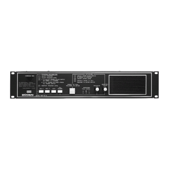
Page 5: Front & Rear Panel Connection Diagrams
Front & Rear Panel Connection Diagrams Front Panel 1. Console MIC - 6. Program/Talk Level - Used for intercom and emergency page functions. Normally LED Indicators: N (normal) lights green to indicate configured (via terminal link) as microphone 1. Provision has been made to option- proper signal level;... -
Page 6: Installation
Auxiliary Power Receptacle An 840-watt, three-wire grounded outlet is provided on the rear panel to supply power to accessory equipment. Auxiliary equipment connected to this outlet will be grounded, provided the MCP35A line cord has been prop- erly grounded. Line-Matching Transformers The MCP35A Master Control Panel is designed for 25-volt constant-voltage distribution systems. -
Page 7: Gain Adjustments (Rear Panel)
(Rear Panel) Model BPA60 provides increased power output. To install, connect a cable terminated in a male phone plug from the MCP35A Line Out jack to the Hi-Z input jack on the rear panel of the amplifier. Connect the 25V output from the amplifier to input jack labeled 25V BAL INPUT. -
Page 8: Associated Equipment
(+) terminal on an external 12V DC power supply. Connect the negative (-) terminal on the power supply to ground on the MCP35A. If more than one SCR25A is used, parallel P12 to each SBA225 Wiring SCR25A. -
Page 9: Twk351 Option
General Wiring See Figure 7 for wiring diagram. Where possible, locate the MCP35A centrally, relative to the rooms being served, in order to minimize the length of speaker cables. Orient the unit so that the operator, program director, or other parties are able to see the controls at all times. -
Page 10: Call Switches And Speakers
The wiring must be completed by connecting the shielded pair from the switch to the terminal strip at the rear of the MCP35A chassis. The polarity of the inner conductors is not critical, but make cer- tain to connect this cable shield to the shield already connected to the ter- minal strip. - Page 11 Figure 11– Schematic Diagram, SBA225 Room Selector Panel Figure 12– Typical Interconnection Diagram Figure 13– Typical Wiring Diagram...
-
Page 12: Technical Specifications
Limited Warranty; Exclusion of Certain Damages The Bogen MCP35A Master Control Panel is warranted to be free from defects in material and workmanship for two (2) years from the date of sale to the original purchaser. Any part of the product covered by this warranty that, with normal installation and use, becomes defective (as confirmed by Bogen upon inspection) during the applicable warranty period, will be repaired or replaced by Bogen, at Bogenʼs option, provided the product is shipped insured and prepaid to: Bogen Factory Service Department, 50 Spring Street, Ramsey, NJ 07446,...
Need help?
Do you have a question about the MCP35A and is the answer not in the manual?
Questions and answers