Table of Contents
Advertisement
1
SAFETY ........................................................ 2
1.1
Safety precautions .............................................................. 2
1.2
Trouble-shooting ................................................................ 2
2
INSTALLATION ............................................ 3
3
OPERATION ................................................. 4
3.1
Control elements................................................................. 4
3.2
Before the first use ............................................................. 7
3.3
Measuring of the hardness of the water ........................... 8
3.4
Setting the temperature...................................................... 9
3.5
Ironing with steam .............................................................. 9
3.6
Ironing without steam....................................................... 10
3.7
Vertical steam.................................................................... 10
3.8
Cleaning & Maintenance................................................... 10
3.9
Storing the appliance........................................................ 12
3.10
Steam gun.......................................................................... 12
3.11
Kind of water to be used .................................................. 13
4
COMPONENTS........................................... 14
4.1
Components of the steam station ................................... 14
4.2
Iron components............................................................... 19
5
FUNCTIONS ............................................... 20
6
REPAIR....................................................... 21
6.1
Dismantling the steam station ......................................... 21
R
E
P
A
I
R
I
N
S
T
R
U
C
T
I
O
N
S
R
E
P
A
I
R
I
N
S
T
R
U
C
T
I
O
N
S
R
E
P
A
I
R
I
N
S
T
R
U
C
T
I
O
N
S
Serie TDS25
6.2
Dismantling the iron ......................................................... 23
6.3
Thermostat control ........................................................... 26
6.4
Measuring the temperature.............................................. 27
7
FAULT DIAGNOSTICS ...............................28
7.1
Easy troubleshooting ....................................................... 28
7.2
Fabric stuck to the sole plate .......................................... 28
7.3
7.4
Water leakage in the iron ................................................. 29
7.5
Drips from the openings .................................................. 30
7.6
The steam does not work................................................. 31
7.7
Water leakage in the steam station ................................. 31
7.8
External parts are broken ................................................ 32
7.9
Problems when dismounting the water tank.................. 32
7.10
Dirt in the openings .......................................................... 33
7.11
The deposit drains by itself (with device off) ................. 34
7.12
Inner tank seal damaged.................................................. 35
7.13
Steam regulator breakages.............................................. 35
7.14
Steam station stop working............................................. 36
8
TECHNICAL SPECIFICATIONS.................37
Seite 1 von 37
Advertisement
Table of Contents

Subscribe to Our Youtube Channel
Related Manuals for Bosch TDS 2510


Summary of Contents for Bosch TDS 2510
-
Page 1: Table Of Contents
Serie TDS25 Dismantling the iron ............23 SAFETY ............2 Thermostat control ............26 Safety precautions .............. 2 Measuring the temperature..........27 Trouble-shooting ..............2 FAULT DIAGNOSTICS .......28 INSTALLATION ..........3 Easy troubleshooting ............28 OPERATION ..........4 Fabric stuck to the sole plate .......... 28 “The sole plate does not reach the right temperature”. -
Page 2: Safety
Only a resilient, steady ironing board should be used. Should the iron SAFETY fall or show signs of not being watertight, it should be examined by the Official Technical Department before being used again. Safety precautions First unplug the electricity cable from the mains socket before filling the tank with water. -
Page 3: Installation
INSTALLATION 204_58300000120957_ARA_EN_E.doc – 29.08.a Seite 3 von 37... -
Page 4: Operation
OPERATION Control elements 204_58300000120957_ARA_EN_E.doc – 29.08.a Seite 4 von 37... - Page 5 204_58300000120957_ARA_EN_E.doc – 29.08.a Seite 5 von 37...
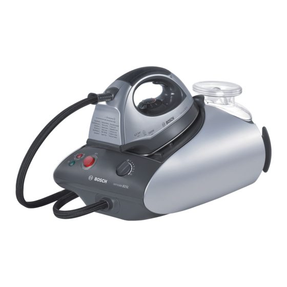
- Page 6 Removable water tank Removable iron pad "Water empty" pilot light "Steam ready" pilot light Illuminated main power On/Off button Steam hose Mains cable with storage facility Illuminated On/Off button for steam generator Variable steam control Housing with intemal steam generator Mains plug Steam hose storage facility Temperature dial...
-
Page 7: Before The First Use
Before the first use 1. Remove any label or protective covering from the sole plate. 2. Place the appliance horizontally on a solid stable surface. You may remove the iron pad from the appliance and place the iron on it on another solid, stable, horizontal surface. 3. -
Page 8: Measuring Of The Hardness Of The Water
Measuring of the hardness of the water In order to determine the hardness of the water used for ironing, there are strips available (ref 056317) that are used as follows: Briefly wet the strip. 2. Shake once. 3. Determine hardness after 1 min: 204_58300000120957_ARA_EN_E.doc –... -
Page 9: Setting The Temperature
Setting the temperature Ironing with steam Check the ironing instruction label on the garment to Make sure that there is enough water in the water tank determine the correct ironing temperature. Turn the temperature selector to the steam position, between Select the temperature (13): "00"... -
Page 10: Ironing Without Steam
Cleaning & Maintenance Ironing without steam After ironing, pull out the plug and allow the appliance to cool Begin ironing but without pressing the steam release button (15). down before cleaning. Wipe the housing, handle and iron body with a damp cloth. Vertical steam If the soleplate is soiled with dirt or scale, clean it with a damp cloth. - Page 11 4. Holding your steam generator in upside down position, and using a jug, fill the boiler (in the base unit) with 1/4 litre of water 5. Shake the base unit for a few moments and then empty it completely over a sink or bucket. To obtain the best result, we recommend that this operation is done twice Important!:...
-
Page 12: Storing The Appliance
2. Fabric stain remover: The concentrator (19) and brush extension Storing the appliance (20) supply a concentrated jet of steam that makes it possible to Always allow the appliance to cool down before storing it. remove certain types of fabric stains. Set the switches for main power and steam boiler to the OFF Preparation: position and disconnect the connection. -
Page 13: Kind Of Water To Be Used
3.10.1 To refresh fabrics Refreshing garments with the steam gun can lessen creases and Attention! wrinkles, although this does not substitute ironing with the iron. For better results, hang the clothes wich you would like to refresh on To avoid damage and/or contamination of the water hangers. -
Page 14: Components
LED “Water needed in tank”: LED that lights up when the COMPONENTS float in the water tank is below a certain level. LED “Steam ready”: LED that lights up when the correct pressure has been reached in the boiler (when the NTC of the Components of the steam station boiler detects a temperature of over 150ºC) On/off switch: Power supply ON/OFF switch of steam station. - Page 15 Water tank outlet valve button: when the tank is fitted, this of this air intake. Without this element, the chamber would not button opens the tank outlet valve. fill up. Water intake valve: when the tank is fitted, the button on the Water outlet tube: This tube takes the water from the bottom opens this valve, enabling the water to flow to the chamber to the pump, which then drives it towards the boiler.
- Page 16 4.1.3 Pump 4.1.4 Solenoid valve Pump: The pump drives the water from the water chamber to the boiler. It is activated in two situations: Solenoid valve: The solenoid valve is normally closed and it ► When the boiler NTC detects a lack of water (Temp opens when the user presses the steam switch of the iron.
- Page 17 4.1.5 Steam cock and air valve 4.1.6 Boiler Boiler: The boiler is the element in charge of heating the water that comes from the tank until steam at the appropriate Air valve: The air valve is in charge of guaranteeing that the pressure is obtained.
- Page 18 After: Checking the NTC: Value of the NTC should be 300kΩ at 20ºC Before: ► Thermofuses (25): As safety elements, the boiler has two series-connected thermofuses that control the temperature of the circuit. ► Water intake (27): Bushing that connects the pump to the boiler.
-
Page 19: Iron Components
Iron components Thermostat: Element in charge of regulating the soleplate temperature according to the selection made by the user on the iron temperature regulator. It is correctly regulated if the shutoff temperature at maximum power (position “ooo” of the regulator) is 180-210ºC in the centre of the soleplate. -
Page 20: Functions
FUNCTIONS 204_58300000120957_ARA_EN_E.doc – 29.08.a Seite 20 von 37... -
Page 21: Repair
REPAIR Dismantling the steam station Remove steam control: Pull control upwards ► Using a flat screwdriver, lever to release the front clips from the trims: Remove side trims: ► Release screws from bottom (Torx 10 “with center hole” , use tip ref 341231) 204_58300000120957_ARA_EN_E.doc –... - Page 22 Remove control front: ► Release the 2 from the top (Torx 10 “with center hole” , use tip ref 341231) ► Raise control front. Remove upper cover: Release the rest of the screws from the casing and lift the cover upwards. ►...
-
Page 23: Dismantling The Iron
Dismantling the iron Release front screw: (Torx 10 “with center hole”, use tip ref Remove temperature control: Pull the control upwards 341231). To do this, remove lens from front LED. Release lower screws: Use tip Torx 10 “with center hole” (ref 341231) Release rear screw: (Torx 10 “with center hole”, use tip ref 341231). - Page 24 Remove the side casing: To do this, release the marked screws and raise the grey casing, pulling it upwards: Remove heel: The heel can be removed by pulling it upwards. At this point the iron hose can be changed: 204_58300000120957_ARA_EN_E.doc – 29.08.a Seite 24 von 37...
- Page 25 Remove the soleplate cover: To do this, release the two marked Allen 3 screws and raise the plastic cover by pulling it upwards: Remove the handle: To do this, release the marked screws and raise the handle by pulling it upwards: 204_58300000120957_ARA_EN_E.doc –...
-
Page 26: Thermostat Control
Thermostat control When the iron thermostats are supplied they have not been regulated, Thermostat as this operation must be carried out with the thermostat mounted inside the steam chamber (soleplate). The easiest way to regulate them is: Mount the new thermostat on the soleplate or steam chamber. The base must be at room temperature. -
Page 27: Measuring The Temperature
Given how important it is to measure the temperature, one of the basic Measuring the temperature tools for repairing irons is the thermometer. A digital thermometer, With all faults preventing the iron from performing its basic function available as a spare part with reference 341176, is specially (fabric stuck to the sole plate, drips trickling out of the steam vents, “it recommended for such purposes. -
Page 28: Fault Diagnostics
FAULT DIAGNOSTICS Easy troubleshooting Fabric stuck to the sole plate Fabric stuck to the sole plate is a sign that the sole plate of the iron has reached a temperature that is too high for that type of cloth. When the temperature is too high, this may be due to two reasons: either the thermostat has been set wrongly or the temperature has not been selected correctly by the user. -
Page 29: The Sole Plate Does Not Reach The Right Temperature
“The sole plate does not reach the right temperature” With this type of complaint, first of all it is necessary to check the temperature of the sole plate, there being two possible outcomes: The temperature is correct: The thermostat is working correctly, if the maximum temperature (“max”... -
Page 30: Drips From The Openings
If the iron heats up, check that maximum power is reached Drips from the openings (position ooo on the temperature regulator), i.e. 180-210ºC. If it Drips from the openings are is not always due to a technical defect: cuts off below this temperature, replace the thermostat and recalibrate it. -
Page 31: The Steam Does Not Work
7.6.2 Iron verification The steam does not work Check general state of iron soleplate. In extreme cases, remains of scale may obstruct the steam outlets. 7.6.1 Verification of the steam station Check the operation of the microswitch of the iron steam button. -
Page 32: External Parts Are Broken
Problems when dismounting the water tank 7.9.1 Problem description On appliances produced before FD8701, the customer may claim that the water tank can hardly be taken out of the appliance. 7.9.2 Cause of the problem The water tank is retained because of a vacuum-effect, since the air cannot enter the tank directly. -
Page 33: Dirt In The Openings
Limescale stains (white or brown) around the openings on the base: In these cases, the limescale is more serious and 7.10 Dirt in the openings could even block the openings on the base. 7.10.1 A product has been added to the water (e.g. perfume, softener, etc...) In these cases, it will be necessary to check the tank and the dosing assembly because characteristic stains of the product that has been... -
Page 34: The Deposit Drains By Itself (With Device Off)
7.11 The deposit drains by itself (with device off) 7.11.1 Description of the problem The water deposit slowly empties with the device switched off (the device absorbs water from the deposit while cooling). 7.11.2 Cause of the problem The defect is due to a lack of ventilation of the boiler; thus, during its cooling, a vacuum is generated inside the boiler which absorbs the water from the deposit. -
Page 35: Inner Tank Seal Damaged
7.12 Inner tank seal damaged 7.12.1 Problem description In devices whit FD<8907, the seal is damaged 7.13 Steam regulator breakages 7.13.1 Problem description In devices whit FD<8904, the steam regulator is broken. 7.12.2 Cause of the problem Wrong cleaning by client (vinegar basis) 7.12.3 Solution Change the seal. -
Page 36: Steam Station Stop Working
7.13.2 Cause of the problem 7.14.2 Cause of the problem There are defects in the mould manufacturing Relay from the PCB failure 7.13.3 Solution 7.14.3 Solution Change the regulator. Change the PCB From FD 8904, the mould of the regulator steam was improved. From FD9209 the supplier of the wrong relay was changed. -
Page 37: Technical Specifications
TECHNICAL SPECIFICATIONS 204_58300000120957_ARA_EN_E.doc – 29.08.a Seite 37 von 37...
Need help?
Do you have a question about the TDS 2510 and is the answer not in the manual?
Questions and answers