Table of Contents
Advertisement
M 7-C / M 17-C / M 27-C
Service Manual
Grundig Service
Hotline Deutschland...
...Mo.-Fr. 8.00-16.30 Uhr
Technik:
TV/SAT
0180/52318-41
VCR/LiveCam
0180/52318-42
HiFi/Audio
0180/52318-43
Car Audio
0180/52318-44
Telekommunikation
0180/52318-45
Fax:
0180/52318-51
Ersatzteil-Bestellannahme:
0180/52318-40
Telefon:
0180/52318-50
Fax:
Zusätzlich erforderliche
Unterlagen für den Komplettservice
Additionally required
Service Manuals for the Complete Service
Service
Service
Manual
Manual
Yacht Boy
Sicherheit
Safety
P 2000
Sach-Nr./Part No.
Sach-Nr./Part No.
72010-757.00
72010-800.00
GRUNDIG Service
Allgemeiner Teil / General Section
Audio
Yacht Boy P 2000
Btx * 32700 #
Sachnummer
Part Number 72010-757.00
Änderungen vorbehalten
Subject to alteration
Printed in Germany
VK231 1197
1 - 1
Advertisement
Table of Contents

Related Manuals for Grundig Yacht Boy P 2000


Summary of Contents for Grundig Yacht Boy P 2000
-
Page 1: Service Manual
M 7-C / M 17-C / M 27-C Allgemeiner Teil / General Section Service Manual Audio Yacht Boy P 2000 Grundig Service Hotline Deutschland..Mo.-Fr. 8.00-16.30 Uhr Technik: TV/SAT 0180/52318-41 VCR/LiveCam 0180/52318-42 HiFi/Audio 0180/52318-43 Car Audio 0180/52318-44 Telekommunikation 0180/52318-45 Fax:... -
Page 2: Table Of Contents
AF Voltmeter Test Generator Oszilloskop Oscilloscope Beachten Sie bitte das GRUNDIG Meßtechnik-Programm, das Sie Please note the Grundig Catalog “Test and Measuring Equipment” unter folgender Adresse erhalten: obtainable from: GRUNDIG electronics GmbH GRUNDIG electronics GmbH Würzburger Str. 150, D-90766 Fürth/Bay Würzburger Str. -
Page 3: Technische Daten
Yacht Boy P 2000 Allgemeiner Teil / General Section Technische Daten Technical Data Spannungsversorgung: Power Supply: Batteriebetrieb: ..........3 x 1,5V (IEC LR 6) Battery operation: ..........3 x 1.5V (IEC LR 6) AC Netzadapter: ..........DC 4,5V ->+ extern AC power adapter: ........ -
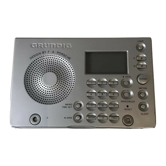
Page 4: Bedienhinweise
Bedienhinweise Dieses Kapitel enthält Auszüge aus der Bedienungsanleitung. Weitergehende Informationen entnehmen Sie bitte der gerätespezifischen Bedienungsanleitung, deren Sachnummer Sie in der entsprechenden Ersatzteilliste finden. BEDIENELEMENTE ANZEIGEFELD Ledereinband Bedienelemente Anzeigefeld Umschalten der Anzeige Ihr YB-P 2000 wird in einem Ledereinband ausgeliefert, der Das Anzeigefeld informiert Sie über die Funktionen Ihres Über die Taste MODE kann die Information, die im Display des DC 4,5 V ->+ –... - Page 5 RADIOEMPFANG RADIOEMPFANG AM STEP-Wahltaste (MW) Radioempfang Einstellen eines Senders Gespeicherte Sender Der minimale ‘Frequenzabstand’ (Reichweitenteilung) zwischen • Vergewissern Sie sich, daß der LOCK-Schalter ausgeschaltet ist. Es gibt drei Möglichkeiten, einen Sender einzustellen: Sie können 20 Sender einprogrammieren, 5 für jeden –...
-
Page 6: Operating Instructions
Operating Instructions This chapter contains excerpts from the operating instructions. For further particulars please refer to the appropriate user instructions the part number of which is indicated in the relevant spare parts list. CONTROLS DISPLAY Leather cover Controls Display Switching the display mode Your YB-P 2000 comes with a leather cover which is used both DC 4.5 V ->+ –... -
Page 7: Preset Radio Stations
RADIO RECEPTION RADIO RECEPTION AM STEP selector (MW) Radio reception Tuning to a station Preset radio stations The minimum ’frequency distance’ (span division) between • Ensure that the LOCK-switch is off. There are three possibilities for tuning in to a station: You can programme 20 stations into the memory, 5 on each adjacent radio stations (measured in kHz) is standardized all –... -
Page 8: Ausbauhinweise
Allgemeiner Teil / General Section Yacht Boy P 2000 Ausbauhinweise Disassembly Instructions 1. Gehäuserückteil 1. Rear Panel - Batteriefachdeckel abnehmen. - Remove the cover from the battery compartment. - 3 Schrauben A herausdrehen (Fig. 1). - Undo 3 screws A (Fig. 1). -
Page 9: Hauptplatte
Yacht Boy P 2000 Allgemeiner Teil / General Section Band Schalter/Switch Mono-Stereo Schalter/Switch Fig. 4 Fig. 5 Fig. 6 3. Hauptplatte 3. Main Board - Chassis ausbauen (siehe Pkt. 2). - Remove the chassis (see para 2). - 2 Schaltschieber F (Fig. 4) und G Fig. 5 vorsichtig abhebeln. - Page 10 Abgleich / Alignment Yacht Boy P 2000 Abgleich Meßgeräte: Meßsender, Wobbelsender, DC-Voltmeter, NF-Voltmeter, Oszilloskop. Abgleichlageplan siehe Seite 2 - 3. Abgleich Vorbereitung Abgleichvorgang 1. AM-ZF AM; eine Frequenz einstellen, auf der kein Sender sendet. Mit T2 Maximum einstellen. Pin5 und Pin6 IC2 mit einem Elko 2,2µF überbrücken (+ an Pin5).
- Page 11 Yacht Boy P 2000 Abgleich / Alignment Alignment Measuring instruments: Signal Generator, Sweep Generator, DC-Voltmeter, AF-Voltmeter, Oscilloscope. Alignment scheme see page 2 - 3. Alignment Preparations Procedure 1. AM IF AM; tune to a frequency where no broadcast station is Adjust T2 to maximum.
- Page 12 Abgleich / Alignment Yacht Boy P 2000 Abgleichlageplan Alignment Scheme Bestückungsseite Component Side Meßpunkte Testpoints TP3 GND Lötseite Solder Side TP5G TP6G 2.2µF 2 - 3 GRUNDIG Service...
-
Page 13: Bedienplatte
Yacht Boy P 2000 Schaltpläne und Druckplattenabbildungen / Circuit Diagrams and Layout of PCBs Yacht Boy P 2000 Schaltpläne und Druckplattenabbildungen / Circuit Diagrams and Layout of PCBs Schaltpläne und Druckplattenabbildungen TO CONNECTOR MAIN BOARD PAGE 3-2 Circuit Diagrams and Layout of PCBs CONNECTOR 0.2V... - Page 14 Schaltpläne und Druckplattenabbildungen / Circuit Diagrams and Layout of PCBs Yacht Boy P 2000 Schaltpläne und Druckplattenabbildungen / Circuit Diagrams and Layout of PCBs Yacht Boy P 2000 Hauptplatte / Main Board TEL. 10.7MHz ANT. 2SC2812 AM-IF FM-IF S 1-2...
- Page 15 Yacht Boy P 2000 Schaltpläne und Druckplattenabbildungen / Circuit Diagrams and Layout of PCBs Yacht Boy P 2000 Schaltpläne und Druckplattenabbildungen / Circuit Diagrams and Layout of PCBs Hauptplatte S 3-A CHIP TRANSISTOR Main Board TOP VIEW IC 3 TA7376P 2SC2812 Lötseite / Solder Side...
-
Page 16: Operating Board
Schaltpläne und Druckplattenabbildungen / Circuit Diagrams and Layout of PCBs Yacht Boy P 2000 Schaltpläne und Druckplattenabbildungen / Circuit Diagrams and Layout of PCBs Yacht Boy P 2000 Bedienplatte Operating Board Lötseite Bestückungsseite Solder Side Component Side CHIP TRANSISTOR TOP VIEW... -
Page 17: Ic Block Diagrams
Yacht Boy P 2000 Schaltpläne und Druckplattenabbildungen / Circuit Diagrams and Layout of PCBs IC-Blockdiagramme IC Block Diagrams IC1 TA7358P TA 7358 P BUFFER LOCAL OSC. VOLTAGE BIAS REGULATOR BIAS IC2 TA8132AF Dec. Decoder AM/FM Mono Sw. Mix. Level Det. -
Page 18: Explosionszeichnung
Ersatzteilliste und Explosionszeichnung / Spare Parts List and Exploded View Yacht Boy P 2000 Ersatzteilliste und Explosionszeichnung / Spare Parts List and Exploded View 4 - 1 GRUNDIG Service... -
Page 19: Ersatzteilliste
CF 4 75954-501.41 FILTER SFZ450C3N 75954-501.43 SCHIEBESCHALTER CF 5 75954-501.42 DISCRIMINATOR CDA10,7MG18 S 201 75954-501.44 SCHIEBESCHALTER 10 / 97 YACHT BOY P 2000 CF 6 75954-065.86 WIDERSTAND KERAMIK CSB456 S 202 75954-501.45 SCHIEBESCHALTER RESISTOR S 203 75954-501.43 SCHIEBESCHALTER S 204 75954-501.43... - Page 20 90471 Nürnberg 09 11/7 03-0 Marketing und Vertrieb Europa GmbH Kundendienst Europa GRUNDIG BELUX N.V. GRUNDIG NORGE A. S. Deltapark Unit 3, Weihoek 3 Glynitveien 25, Postboks 234 B-1930 Zaventem N-1401 00 32-2-7 16 04 00 00 47-64 87 82 00 GRUNDIG OY GRUNDIG INTERNATIONAL LTD.
Need help?
Do you have a question about the Yacht Boy P 2000 and is the answer not in the manual?
Questions and answers