Table of Contents
Advertisement
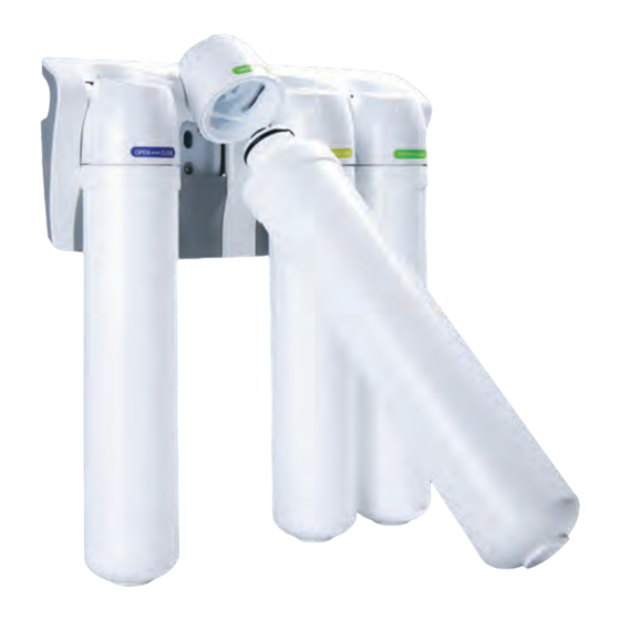
RO
FILTRATION
SYSTEM
4STAGE
Note : Please read through the instructions carefully before using or installing the product
and ensure that the manual is kept in a safe place for future reference.
The system must be properly installed and located in accordance with the installation
instructions before it is used.
Advertisement
Table of Contents

Related Manuals for Safeway water 4 Stage Ro

Summary of Contents for Safeway water 4 Stage Ro
- Page 1 FILTRATION SYSTEM 4STAGE Note : Please read through the instructions carefully before using or installing the product and ensure that the manual is kept in a safe place for future reference. The system must be properly installed and located in accordance with the installation instructions before it is used.
- Page 2 Installation & Maintenance Guide...
-
Page 3: Safety Instructions
1. Safety Instructions Attention M9 QUICK CHANGE RO WATER FILTRATION SYSTEM Customer This system is intended for use on potable water supplies or disinfected water containing cysts. Do not use where water is microbiologically unsafe or with water of unknown quality. If bacterial contamination is present, a recognized method of water disinfection is required. -
Page 4: Specifications
2. Specifications Stage 1 Stage 2 Stage 3 Stage 4 Storage Tank Faucet Reverse Osmosis NCPV 893 Sediment Filter Activated Carbon Filter Activated Carbon Filter TP-12P Membrane CP-KR01 Daily Production Rate* L/day (G/day) 76.8(20.3) Typical System Flow Sequence Sediment Filter Activated Carbon Prefilter ... - Page 5 Replacement Cartridge FILTER CARTRIDGES FUNCTION RATED LIFE CAPACITY Sediment filter 11" Particulate, dirt & sand GAC (Granular Activated Chlorine, taste and odor 1,500 Gallons (5,678 Liters) 6 months or 12 months Carbon) filter 11" Particulate, dirt & sand Carbon block filter 11" 1,500 Gallons (5,678 Liters) hlorine, taste and odor RO membranes filter 11"...
-
Page 6: Arsenic Facts
Recommended Influent Water Characteristic Notes System Pressure 40 - 100 psi (2.8 - 7kgf/cm 1. The reverse osmosis membrane used in these systems may be damaged by chlorine. These systems include Temperature 40 - 100 °F (4 - 38 °C) activated carbon filters which protect the membranes by reducing chlorine. -
Page 7: Installation Instructions
3. Installation Instructions TYPICAL INSTALLATION DIAGRAM NCPV 893 CP-KR01 1/4” Blue Tube 1/4” Angle Stop Adaptor Valve(ASVPP1) 1/4” Orange Tube 1/4” Drain Saddle Valve 1/4” Black Tube J.G Tank Shut Off Valve 1/4” White Tube Pressure Tank TP-12P I Installation & Maintenance Guide 5... -
Page 8: Step 1 - Select Component Installation Locations
Step 1 – Select Component Installation Locations • Dispenser Faucet – The faucet is designed to be mounted on the rear lip of the sink. It may be installed in an existing sprayer attachment hole or in a hole drilled at the time of installation. It may also be mounted to an adjacent counter top. -
Page 9: Step2. Faucet Installation
Step2. Faucet Installation The M9 QUICK CHANGE RO WATER FILTRATION SYSTEM features reliable and convenient push-to-connect tubing connectors. Tubing is easily connected and disconnected from these fittings as follows. To simplify its access and installation, we suggest you install the faucet on the rear lip of the sink. It should be evenly positioned with the sink faucet and spray attachment. - Page 10 Step 3 – Install Adapter Valve on Water Supply(ASVPP1) CAUTION! The Adapter valve should be connected to cold water supply only. Connection to hot water supply will damage the system and will void all warranty Cold Water Verify the gasket is Line to properly seated Faucet...
- Page 11 4. Attach 1/4” black tube by slipping the tube through the black compression nut and hand tighten the nut on to the saddle valve. CAUTION! The drill should be kept straight and centered to avoid damaging the saddle valve. Many homes are equipped with disposals and dishwashers.
- Page 12 Performance & Technical Information The performance of the M9 RO System can be characterized and judged by the quality and quantity of the water produced by the system. By measuring the contaminant removal performance and flow rates of the system, its operating status can be easily evaluated.
-
Page 13: Troubleshooting Guide
Troubleshooting Guide If a problem cannot be corrected through the use of this troubleshooting guide : • Serial # • Model # Problem Possible Cause Remedy 1. Insufficient quantity a. Service greater than unit’s specified output. a. Use optional large tank for more storage of product water capacity. - Page 14 Problem Possible Cause Remedy 8. Bad smell from a. Polishing filter exhausted. a. Replace polishing filter. product water. b. Prefilter element. b. Replace filter element. c. Unit needs disinfection. c. Sanitize unit. 9. Fast flow to drain. a. Defective flow control assembly. a.
-
Page 15: Limited One-Year Warranty
4. Limited One-year Warranty Limited One-year Warranty Any defect tn materials or workmanship in the manufactured product. What does this warranty not cover? 1. Improper installation, delivery or maintenance. 2. Failure of the product if it is abused misused, altered, used commercially or used for other than the intended purpose. -
Page 16: Filtration System
FILTRATION SYSTEM...
Need help?
Do you have a question about the 4 Stage Ro and is the answer not in the manual?
Questions and answers