Table of Contents
Advertisement
8716 W. Ludlow Drive Suite 1
Peoria, Arizona 85381
Phone: (800) 752-5582
www.wattspremier.com
Tools and Fittings Required
• Pipe Cutter
• Tubing Cutter
• File
• Pliers
• Tape Measure
• Soldering Tools
• Lead Free Solder
• Bucket
• Towel
• Plumber Tape
• Adjustable Wrench
• Tube 100% Silicone Grease
Tested and Certified by the WQA against
NSF/ANSI Standard 44 for Softener Performance
& NSF/ANSI 372 for "lead free" compliance.
For further operating, installation, maintenance, parts or assistance:
Call Canadian Based Customer Service at: (905) 332 4090
Call US Based Customer Service at: (408) 675 7995 or (800) 752-5582
©2012 Premier • Printed in U.S.A.
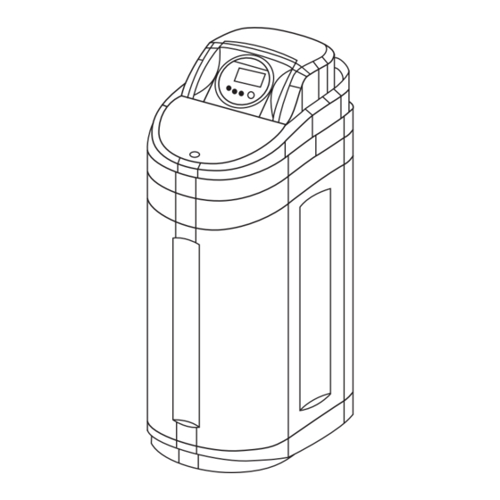
Model AF-40K
Water Softening System
INSTALLATION INSTRUCTIONS
Installation Instructions . . . . . . . . . . . . . . . . . Pages 2-13
Repair Parts. . . . . . . . . . . . . . . . . . . . . . . . . Pages 14-17
167041 Rev B
MR12
Advertisement
Table of Contents

Related Manuals for Premier AF-40K


Summary of Contents for Premier AF-40K
- Page 1 & NSF/ANSI 372 for "lead free" compliance. For further operating, installation, maintenance, parts or assistance: Call Canadian Based Customer Service at: (905) 332 4090 Call US Based Customer Service at: (408) 675 7995 or (800) 752-5582 ©2012 Premier • Printed in U.S.A. 167041 Rev B MR12...
-
Page 2: Table Of Contents
The person installing this equipment • Operating ambient temperature is between 34°F (1°C) should have: and 120°F (49°C). • Knowledge in the Premier series controller and water • Operating water temperature is between 35°F (1°C) and softener installation 100°F (38°C). - Page 3 Any remaining brine residual is rinsed from the resin bed. Figure 2 Top of Unit Display Time of Day Recharge Button Button Salt Amount Button Water Hardness Button Figure 3 Control Front Premier AF-40K MR12 • 3...
- Page 4 It is recommended that the system be installed indoors. When the water conditioning system must be installed outdoors, several items must be considered. • Moisture — The valve and Premier controller are rated for NEMA 3 locations. Falling water should not affect performance.
- Page 5 Outside Faucet Faucet Hot Water Grounding Soft Water Outlet Strap Hard Water Bypass Drain Line Water Heater Softener Brine Tank Over ow Drain Laundry Tubs Pump Meter Floor Drain Figure 7 Softened Water Flow Diagram Premier AF-40K MR12 • 5...
- Page 6 • Check that all O-rings are in place and not damaged. • Lubricate O-rings and sliding surfaces with 100% silicone. Firmly insert connector into bypass. Press locking clip into position. Make certain the clip is fully engaged. 6 • MR12 Premier AF-40K...
- Page 7 7 inch (18 cm) loop at the far end of the line so that the bottom of the loop is level with the drain line connection. This will provide an adequate siphon trap. Premier AF-40K MR12 • 7...
-
Page 8: System Disinfection
B. Proceed with the normal recharge. All Premier Series controllers operate on 12-volt alternating current power supply. This requires use of the proper supplied *Clorox is a trademark of the Clorox Company. -
Page 9: General Premier Series Instructions
NOTE: In normal operation and during programming, only All programmed parameters are stored in the Premier Series a few of the icons will actually be displayed. static memory and will not be lost in the event of a power 1. -
Page 10: Keypad - Buttons
Fast Rinse 2 3 min 3 min 3 min *The camshaft does not move between cycles 4 and 5. Cycle 5 begins when the brine in the salt tank runs out and the check valve closes. 10 • MR12 Premier AF-40K... -
Page 11: Premier Series Initial Power-Up
Figure 19 Step 1 Drain (gpm) 2. Pick the salt setting - The controller starts (defaults) with PREMIER SERIES INITIAL POWER-UP the HE (high efficiency) setting. If you want to check or change the setting, press the Salt Amount button to display The water supply valve should be off or the valve is in by-pass the current setting. -
Page 12: Placing Softener Into Operation
• The inlet water is off and the bypass is not in bypass Both valve handles pointing in direction of water flow If any of the above are not true please correct the item before proceeding further. 12 • MR12 Premier AF-40K... -
Page 13: Placing Softener Into Operation (Turning On The Water)
The water in the salt tank Accessing History Values will lower. If water is leaving the salt tank, advance to the The Premier control features a review level that displays the next cycle. operation history of the system. This is a great troubleshooting 8. -
Page 14: Tank Assembly
2 ..... 1 ..213126... Housing 3 ..... 1 ..313012... Lid 4 ..... 1 ..367202... Latch 5 ..... 1 ..167028... Controller, AF-40K 6 ..... 1 ..367026... Resin Tank 7 ..... 1 ..367203... Brine Tube Assembly 8 ..... 1 ..249033... Clamp, Resin Tank 9 ..... -
Page 15: Valve Assembly
Item No. QTY Part No. Description 14 ... 1 ..622013... Assembly, Refill Cont, .33 1 ..... 1 ..367208... Assembly, Premier Controller Cover 15 ... 2 ..622014... Ball, Backwash, Brine Refill 2 ..... 1 ..116182 ... Valve Body Assy, Volumetric Controller Includes Item #18 16 ... -
Page 16: Brine Well Assembly Ch20795
8 ..... 2 ..231049... Tubing Insert, Brass Not Shown 1 ..231056... Overflow Fitting Assembly 1 ..*231057 ..Overflow Elbow 1 ..*231058 ..Overflow Nut 1 ..*252234 ..Gasket *Parts included with CH20774 Overflow Fitting Assembly 16 • MR12 Premier AF-40K... -
Page 17: Troubleshooting
TROUBLESHOOTING Premier Control - Error Codes Problem Possible Cause Solution Err 1 is displayed. Press any key. If Err 1 does not clear, replace control. Program settings have been corrupted. Err 3 is displayed. Control does not detect the camshaft position and is Wait until the control returns to the service position. - Page 18 TROUBLESHOOTING continued Valve Disc Operation When the Premier control is lifted up (Figure 22 Control Removed) and the cover is removed, the flappers and camshaft are visible (Figure 23 Valve Layout). Figure 22 Control Removed Injector Cap Refill Control Cap Figure 23 Valve Layout 18 •...
-
Page 19: Premier Limited Warranty
Premier or a Premier authorized dealer (8) noncompliance with applicable codes/ ordinances. If a defect in workmanship or materials in a product or part covered by the warranty should arise, Premier at its sole discretion, will repair or replace the defective product or part. -
Page 20: Performance Data Sheet
Refer to the system Installation and Service Manuals for by the WQA against set-up and programming instructions. Contact your local Premier dealer for parts and service. NSF/ANSI Standard See your owner’s manual for warranty information.
Need help?
Do you have a question about the AF-40K and is the answer not in the manual?
Questions and answers