Advertisement
Quick Links
Download this manual
See also:
Installation Manual
Advertisement

Related Manuals for DCI C1103

Summary of Contents for DCI C1103
- Page 1 Compressor Service & Maintenance Manual C Series C Series COMPRESSOR COMPRESSOR • (D)C1103 • (D)C1103 • (D)C1203 • (D)C1203 • (D)C2106 • (D)C2106 • (D)C2206 • (D)C2206 • (D)C3210 • (D)C3210 Copyright © 2006 DCI. All Rights Reserved. 92311, Rev. C, 08/13...
- Page 2 w w w. d cio nl i n e. com w w w. d c i o n li n e.com...
- Page 3 C1000 Series Service & Maintenance Manual SECTION I Introduction Compressor Service, Maintenance, and Parts Manual Section I: INTRODUCTION A. General Specifications Section II: THEORY OF OPERATION A. While Running B. Theory of Operation While Not Running Section III: MAINTENANCE A. Compressor Head Intake Filter B.
- Page 4 Introduction This manual contains the necessary information to perform all “fi eld serviceable” aspects of the DCI Oil-less Air Compressor line. Please take the time to read this manual and understand the proper operation and service procedures before attempting to service this machine.
- Page 5 INTRODUCTION This manual contains the necessary instructions for the maintenance and/or service of the DCI air compressors. There are 3 basic confi gurations available; single and dual head available in 115V and 230V, and the triple head available in 230V.
-
Page 6: Model Specifications
C1000 Series Service & Maintenance Manual Introduction Unpacking Model Specifi cations MODEL SPECIFICATIONS Model CFM @ 80PSI Total HP Tank Capacity Dimensions (inches) Voltage Amps Circuit Breaker C1103 3.95 29.5 13.4 C1203 3.95 29.5 C2106 7.95 29.5 26.8 C2206 7.95 29.5... -
Page 7: Theory Of Operation
C1000 Series Service & Maintenance Manual SECTION II Theory of Operation Theory of Operation THEORY OF OPERATION While Running To start the compressor, the user shall activate the compressor head or heads with the power switches located on the front center of the machine. - Page 8 Drying System Tank Pressure Gauge correctly. By purging the drying chamber on a time basis, the DCI air compressors ensure the drying chamber desiccant remains dry, Strainer even during heavy usages, for consistent air quality. Shutoff...
- Page 9 C1000 Series Service & Maintenance Manual SECTION II Theory of Oporation Theory of Operation THEORY OF OPERATION While Not Running Electrical Schematic 1 . 8 0 0 . 6 2 4 . 2 7 9 3...
- Page 10 Every six months, remove the intake fi lter cover as shown in (Fig. D), to check for excessive dirt or discoloration. Replace with DCI Part Number 2012 if needed. The fi lters are located on the rear of each compressor cylinder.
- Page 11 ON position “parallel with fl oor”. Check the fi lter screen inside the fi lter / strainer valve as shown in Fig. G. If the strainer / shutoff valve is on and the screen is not clogged, replace the Time Operated Purge Valve with DCI part Number 2011 for 230 volt models, or DCI Part number 2848 for 115 volt models.
-
Page 12: Troubleshooting Chart
SECTION IV C1000 Series Service & Maintenance Manual Service and Repair Unpacking Troubleshooting Chart TROUBLESHOOTING CHART SYMPTOMS CAUSES POSSIBLE REMEDY Compressor Will Not Run No Power Check circuit breaker. Improper Line Voltage Ensure that supply voltage matches equipment ratings. Tripped Overload Check for loose wiring. - Page 13 C1000 Series Service & Maintenance Manual SECTION IV Service and Repair Unpacking Troubleshooting Chart TROUBLESHOOTING CHART SYMPTOMS CAUSES POSSIBLE REMEDY Compressor Overheats Clogged Air Intake Filter Clean or replace intake fi lter element. Exhaust Valve Clean & Replace valve-plate. Too Much Run Time Air leaks;...
- Page 14 C1000 Series Service & Maintenance Manual SECTION IV Service and Repair Unpacking Electrical ELECTRICAL A. Electrical Components 1. Pressure Switch: Turns on or off the power supplied to the individual compressor motor switches. The pressure switch is preset to run the compressors to 100psi and then open, therefore stopping the motor(s).
- Page 15 C1000 Series Service & Maintenance Manual SECTION IV Service and Repair Unpacking Electrical 2. Power Switches: The toggle switches located on the front center of the compressor control the individual compressor motors. If the pressure switch is operating correctly, remove the motor terminal cover on the back of the desired compressor motor.
- Page 16 2. Turn “OFF” the strainer / shutoff valve in Fig. N. 3. Remove the valve and replace with DCI Part Number 2011 for 230 volt machines OR DCI Part Number 2848 for 115 volt models. 4. Return the strainer / shutoff valve to the On position.
- Page 17 C1000 Series Service & Maintenance Manual SECTION IV Service and Repair Unpacking Electrical PNEUMATIC WARNING: HIGH SYSTEM PRESSURES MAY CAUSE SERIOUS INJURY. ALWAYS DEPRESSURIZE THE ENTIRE SYSTEM BEFORE ATTEMPTING TO SERVICE PNEUMATIC COMPONENTS. 1. Replacing the check valves. If a check valve failure occurs, the symptom will be air escaping through one of the compressor heads with the compressor NOT running.
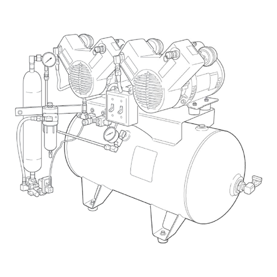
- Page 18 SECTION V C1000 Series Service & Maintenance Manual Illustrated Parts Breakdown Unpacking Parts Call-Out 2005 Pressure 2013 Switch Relief Valve 2012 2856 Intake Element Pressure Gauge 2135 2002 Check Valve 1 hp Head Data Tag Outlet Ball Valve 2856 Pressure Gauge 2859 Petcock Valve 2014...
- Page 19 C1000 Series Service & Maintenance Manual SECTION V Illustrated Parts Breakdown Unpacking Electrical Schematic 1 . 8 0 0 . 6 2 4 . 2 7 9 3...
- Page 20 SECTION V C1000 Series Service & Maintenance Manual Illustrated Parts Breakdown Unpacking Plumbing Schematic Left Right Motor Motor Check Check Aftercooling Valve Valve Tubing Coalescing Filter Dryer Bypass Ball Valve Flow/Check Condensate Drain Storage Drying System Tank Pressure Gauge Strainer Shutoff Valve Time Purge...
- Page 21 1 . 8 0 0 . 6 2 4 . 2 7 9 3...
- Page 22 305 N. Springbrook Road Newberg, Oregon 97132 USA 503.538.8343 800.624.2793 www.dcionline.com...
Need help?
Do you have a question about the C1103 and is the answer not in the manual?
Questions and answers