
Related Manuals for Chassis Plans CPX-15

Summary of Contents for Chassis Plans CPX-15
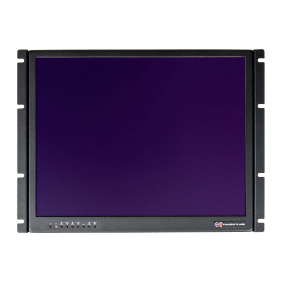
- Page 1 CPX-15 CPX-17 CPX-19 Rugged Military Grade 8U Rack Mount LCD Display 15” XGA TRANSFLECTIVE LCD 17” or 19” SXGA LCD Technical Reference 22010100B Revision B October 8, 2014...
- Page 3 In no event shall Chassis Plans be liable for any defect in hardware or software or loss or inadequacy of data of any kind, or for any direct, indirect, incidental or consequential damages arising out of or in connection with the performance or use of the product or information provided.
- Page 4 This manual is as complete and factual as possible at the time of printing; however, the information in this manual may have been updated since that time. Chassis Plans reserves the right to change the functions, features or specifications of their products at any time, without notice.
- Page 5 CAUT ION: The ligh hting flash with h arrowhead symbol inside e an equilater ral triangle is inten nded to alert t the user to th e presence o of uninsulated , dangerous v voltage which may be of su fficient magn itude to const titute a risk of...
-
Page 6: Table Of Contents
Index Chassis Plans CPX-15, -17, -19 Technical Reference Table of Contents Chapter 1 ‐ Introduction _______________________________________________________________ 1 Description _______________________________________________________________________________ 1 Table 1 – Display Specifications ____________________________________________________________________ 1 CPX Part Number Matrix _ ____________________________________________________________________ 2 Table 2 – CPX Part Number Matrix _________________________________________________________________ 2 LCD Enhancements _________________________________________________________________________ 3 Figure 1 – EMI Shielding Effectiveness of ITO Coating __________________________________________________ 3 Figure 2 – Optical Stack on LCD ____________________________________________________________________ 3 Figure 3 – Comparison of Reflections with and without Optical Bonding ___________________________________ 4 ... - Page 7 Index Chassis Plans CPX-15, -17, -19 Technical Reference Chapter 3 – Installation _ ______________________________________________________________ 14 Product Contents _ _________________________________________________________________________ 14 Rack Installation __________________________________________________________________________ 14 Figure 6 ‐ Rack Mounting Hole Spacing _____________________________________________________________ 14 Connecting the Display _____________________________________________________________________ 15 Standard Controller Rear Panel Connections ___________________________________________________ 15 Figure 7 ‐ Standard Controller Rear Panel I/O ________________________________________________________ 15 Table 9 ‐ Rear Panel Connections – Standard Controller _______________________________________________ 15 Advanced Controller Rear Panel Connections _ __________________________________________________ 16 Figure 8 ‐ Advanced Controller Rear Panel I/O _______________________________________________________ 17 Table 10 ‐ Rear Panel Connections – Advanced Controller ______________________________________________ 17 Chapter 4 – Operation ________________________________________________________________ 18 ...
- Page 8 Index Chassis Plans CPX-15, -17, -19 Technical Reference Network configuration _____________________________________________________________________ 44 Image D‐2 – Network Drop Down _________________________________________________________________ 44 Image D‐3 – Network Configure Settings ___________________________________________________________ 45 Connect to a single CPX Family _ ______________________________________________________________ 45 Table D‐1 – Remote Control _ _____________________________________________________________________ 45 Image D‐4 – IP Address Locator ___________________________________________________________________ 46 Image D‐5 – IP Address Setting and Enable _ _________________________________________________________ 46 Connect to multiple CPX Family ______________________________________________________________ 46 Table D‐2 – Remote Control _ _____________________________________________________________________ 46 Image D‐6 – DHCP Table Screenshot _______________________________________________________________ 47 Image D‐7 – NAT Fowarding Screenshot ____________________________________________________________ 47...
- Page 9 Index Chassis Plans CPX-15, -17, -19 Technical Reference This Page Intentionally Blank...
-
Page 10: Chapter 1 - Introduction
As with all Chassis Plans products, a wide variety of custom options can be configured per customer or application specific requirements. Contact your Sales Engineer to discuss your particular requirements. -
Page 11: Cpx Part Number Matrix
Chassis Plans CPX-15, -17, -19 Technical Reference Chapter 1 - Introduction CPX Part Number Matrix Product Family Head Unit Controller Option Power Input CPX1 = CP Panel Extreme 151A = 15” LCD with EMI Shield A1 = Advanced A = AC 110V Controller 151B = 15”... -
Page 12: Lcd Enhancements
In order to not only ruggedize the LCD, but to also enhance the mechanical, optical and EMI properties of the finished unit, as an option, Chassis Plans optically bonds one 3mm AR or two layers of coated 1.1 mm soda-lime float glass to the front of the LCD panel. - Page 13 Chassis Plans s CPX-15, -17 7, -19 Technic cal Reference apter 1 - Intro oduction Witho ut Optical Bondi With Optical Bonding Or AR Coating d AR Coating Reflected Refle cted Light 0.3% 4.5% Total 0.1% 0.7% 22.5 4.5% 4.5% 0.1%...
-
Page 14: Genesis Based Lcd Controllers
Chassis Plans CPX-15, -17, -19 Technical Reference Chapter 1 - Introduction Genesis Based LCD Controllers The LCD Controller is a key component in any display system and no expense has been spared in specifying the Standard Controller and Advanced Controller Genesis controllers. These are long life revision controlled military grade components. -
Page 15: Specifications
Chassis Plans CPX-15, -17, -19 Technical Reference Chapter 1 - Introduction Specifications Enclosure 8U (13.97”) x 3.2” deep Power Supply Options Construction: 5052 aluminum alloy AC Input All stainless steel hardware 100 to 260VAC, auto selecting All self-locking pressed in fasteners where... -
Page 16: Environmental
Chassis Plans CPX-15, -17, -19 Technical Reference Chapter 1 - Introduction Environmental Designed to meet or exceed MIL-STD-810G to the below specifications. ALTITUDE BLOWING SAND AND DUST 10,000 ft. Operational, Procedures I and II 30,000 ft. Storage MIL-STD-810, Method 510.5 MIL-STD-810, Method 500.5... -
Page 17: Standard Controller Dvi-D/Vga Input Features
Chassis Plans CPX-15, -17, -19 Technical Reference Chapter 1 - Introduction Standard Controller DVI-D/VGA Input Features: Advanced Controller Multi- Input Features: Inputs: Inputs: Analog RGB: 60Hz at SXGA, WXGA, XGA, Analog RGB: 60Hz @ UXGA SVGA, VGA 75Hz @ SXGA, WXGA, SVGA, VGA... -
Page 18: Figure 5 ‐ Cpx Outline Drawing
Chassis Plans CPX-15, -17, -19 Technical Reference Chapter 1 - Introduction Figure 5 - CPX Outline Drawing Page 9... -
Page 19: Ac Input Power Supply
Chassis Plan ns CPX-15, -1 7, -19 Techn ical Referenc Chapter 2 – Po ower Supply Options Chapter 2 – Pow wer Supp ply Optio AC Input P Power Su upply he AC Input P Power Supply y is a 65W Me edical Grade “Brick”... -
Page 20: Chapter 2 - Power Supply Options
Chassis Plans CPX-15, -17, -19 Technical Reference Chapter 2 – Power Supply Options 12VDC Input Transient Filter The CPX family display consoles require nominal +12VDC at 40W for operation. An EMI line filter is provided to limit EMI emissions and to provide a small measure of input filtering. -
Page 21: Mil-Std-704/1275 Dc Input Converter
Chassis Plans CPX-15, -17, -19 Technical Reference Chapter 2 – Power Supply Options MIL-STD-704/1275 DC Input Converter The xx Mil-Std-704/1275 DC Input Converter provides true 704/1275 input specifications allowing reliable operation from nominal 28VDC input mains in a military environment. Amil grade DC to DC Converter is provided in a rack mountable case with military grade circular connectors. -
Page 22: +/-48Vdc Power Supply
Chassis Plans CPX-15, -17, -19 Technical Reference Chapter 2 – Power Supply Options +/-48VDC Power Supply The xx 48VDC Input Converter provides universal isolated 48VDC input, either positive or negative input. Thus it can be used in a data center with centralized power of +48VDC as well as a central office with -48VDC mains. -
Page 23: Product Contents
Chassis Plan ns CPX-15, -1 7, -19 Techn ical Referenc hapter 3 – Ins stallation Chapter 3 – Insta allation Product C Contents lease verify a all the followin ng parts are in ncluded in the e packaging fr rom Chassis Plans. -
Page 24: Connecting The Display
Chassis Plan ns CPX-15, -1 7, -19 Techn ical Referenc hapter 3 – Ins stallation Connectin ng the Dis splay he CPX-15. - 17, -19 provid de for two con ntrollers, stan ndard and adv vanced, with r rear panel de etails provided d below. -
Page 25: Advanced Controller Rear Panel Connections
Chassis Plan ns CPX-15, -1 7, -19 Techn ical Referenc hapter 3 – Ins stallation Advanced d Control ller Rear P Panel Co onnection he Advanced Controller pr rovides for VG GA analog, DV VI-D, HDMI, Composite and d S-Video vid eo inputs. -
Page 26: Chapter 3 - Installation
Chassis Plans CPX-15, -17, -19 Technical Reference Chapter 3 – Installation Figure 8 - Advanced Controller Rear Panel I/O Legend Function Connector 12VDC Power Input Power, 12VDC +/-5% Circular Mil N/S 3102A-10SL-3P Composite Video Composite Video Input DVI-D Input DVI-D Video Input... -
Page 27: Lcd Front Panel Controls
Chassis Plan ns CPX-15, -1 7, -19 Techn ical Referenc hapter 4 – Op peration Chapter 4 – Ope eration LCD Fron t Panel C Controls he On Screen n Display (OS SD) is adjuste ed as follows: 1. Press... -
Page 28: Standard Controller Osd Menus
Chassis Plan ns CPX-15, -1 7, -19 Techn ical Referenc hapter 4 – Op peration Standard Controlle er OSD M Menus Sele ect input source Input sou urce 1 Select input s source to Analog g RGB Input sou urce 2... -
Page 29: Osd Menus
Chassis Plan ns CPX-15, -1 7, -19 Techn ical Referenc hapter 4 – Op peration Posi ition Autosetu Auto adjust th he positions, pha ase, frequency Frequenc Adjust the im age horizontal s Phase* Fine tune the e data sampling p... -
Page 30: Advanced Controller Osd Menus
Chassis Plan ns CPX-15, -1 7, -19 Techn ical Referenc hapter 4 – Op peration Advanced d Control ller OSD M Menus cture : Volume Increase/d decrease volume e level, total: 100 steps Brightness Increase/d decrease panel b brightness level, t... - Page 31 Chassis Plan ns CPX-15, -1 7, -19 Techn ical Referenc hapter 4 – Op peration put : Select the i nput video signa D/SD SDI 1 D/SD SDI 2*** omposite 1 omposite 2*** Video D Component Press “-“ key to activate the “Aut...
- Page 32 Chassis Plan n s CPX-15, -1 7, -19 Techn ical Referenc hapter 4 – Op peration ilities : tup to Picture Setup : Auto adju ust the image po osition, phase an nd size to Color Gain : Auto Col...
- Page 33 Chassis Plan n s CPX-15, -1 7, -19 Techn ical Referenc hapter 4 – Op peration olor Temperatur re R Gain : G Gain : B Gain : Reset to Defaults : Resum me to the default t values...
-
Page 34: Appendix A - Display Serial Control Programming
The RS-232 program can be custom-tailored to fit the application or it can be used as provided by Chassis Plans on request. Please contact Chassis Plans for additional information. Table 13 - Standard Controller Commands to Implement Switch Mount Control Buttons... -
Page 35: Table 14 ‐ Standard Controller Parameter Setting ‐ Immediate, Relative, Reset And Query
Chassis Plans CPX-15, -17, -19 Technical Reference Appendix A – Display Serial Control Programming Table 14 - Standard Controller Parameter Setting - Immediate, Relative, Reset and Query Function Command Description Acknowledge (if enabled) Brightness 0x81, Set brightness = Brightness. control nn | “+”... - Page 36 Chassis Plans CPX-15, -17, -19 Technical Reference Appendix A – Display Serial Control Programming Green level for 0xb5, Set the level of the green Green level for selected selected channel for the selected colour temperature. colour nn | “+” | “-” | colour temp.
-
Page 37: Table 15 ‐ Standard Controller Other Control
Chassis Plans CPX-15, -17, -19 Technical Reference Appendix A – Display Serial Control Programming Table 15 - Standard Controller Other Control Function Command Description Acknowledge (if enabled) Select RS- 0xc1, “0” | “1” Disable/enable command “0” – acknowledge acknowledge. disabled. -
Page 38: Advanced Controller Serial Control Functions
The OSD functions are controlled through the following RS-232 or Ethernet commands. The RS-232 program can be custom-tailored to fit the application or it can be used as provided by Chassis Plans on request. Please contact Chassis Plans for additional information. - Page 39 Chassis Plans CPX-15, -17, -19 Technical Reference Appendix A – Display Serial Control Programming Phase (tuning) 0x85, Set dot clock phase = Dot clock phase. control nn | “+” | “-” | (In PC mode only) “?” value/increment/decrement Query Image H...
- Page 40 Chassis Plans CPX-15, -17, -19 Technical Reference Appendix A – Display Serial Control Programming 0x92, Set OSD transparency = OSD tranparency. Transparency n | “+” | “-” | “r” | “R” | value/increment/decrement “0” – ON “?” Reset “1” - OFF...
- Page 41 Chassis Plans CPX-15, -17, -19 Technical Reference Appendix A – Display Serial Control Programming Video System 0x9b, Set video system = Query (Composite, S- “0” | “1” | “2” | Auto/NTSC/PAL/SECAM “0” – Auto. video and “3” | Reset “1” – NTSC_M_358 Component “r”...
- Page 42 Chassis Plans CPX-15, -17, -19 Technical Reference Appendix A – Display Serial Control Programming “F” – Orientation “G” – Hue “H” – Backlight Runtime 0xa1, runtime counter value = Runtime = nnnnn. counter nnnnn | nnnnn (* 0.5 hour) “r” | “R” | Reset “?”...
- Page 43 Chassis Plans CPX-15, -17, -19 Technical Reference Appendix A – Display Serial Control Programming Zoom level 0xa8, Set Zoom level = Zoom level. nnnn | “+” | “-” | “r” | “R” | value/increment/decrement Min : 0x30 0x30 0x30 0x30 “?”...
- Page 44 Chassis Plans CPX-15, -17, -19 Technical Reference Appendix A – Display Serial Control Programming Vertical Pan 0xb2, Set Vertical pan position Scalar vertical pan position for Aspect Size = nnn | “+” | “-” | value/increment/decremen PAL(576i) / NTSC (480i) : “r”...
- Page 45 Chassis Plans CPX-15, -17, -19 Technical Reference Appendix A – Display Serial Control Programming Graphic vertical 0xba Vertical sync frequency (in “nnnc” = vertical frequency sync frequency units of Hz) in 3 digit hex nnn = 3 digit hex enquiry number and 1 char c= “i”...
- Page 46 Chassis Plans CPX-15, -17, -19 Technical Reference Appendix A – Display Serial Control Programming Color 0xe2 Off/ “0” – Off Monochrome “0” | “1” | “2” | “3” Blue Only/ “1” – Blue Only mode selection Red Only/ “2” – Red Only (Output | “4”...
-
Page 47: Table 18 ‐ Advanced Controller Other Control
Chassis Plans CPX-15, -17, -19 Technical Reference Appendix A – Display Serial Control Programming Green Offset 0xe9, Set the Offset of the green Green Offset for selected for selected channel for the selected colour temperature. colour nn | “+” | “-” | colour temp. - Page 48 Chassis Plans CPX-15, -17, -19 Technical Reference Appendix A – Display Serial Control Programming “0”,”0” : invalid “A”,”1” ARGB “B”,”1” Composite “B”,”2” Composite2 “C”,”1” S-video “C”,”2” S-video2 “D”,”1” SD Component “D”,”2” SD Component2 “E”,”1” HDSDI “E”,”2” HDSDI2 “F”,”1” DVI “xx,nn”= PIP input status: “0”,”0”: invalid...
-
Page 49: Table 19 ‐ Hex To Ascii Conversion Table
Chassis Plans CPX-15, -17, -19 Technical Reference Appendix A – Display Serial Control Programming ASCII ASCII ASCII ASCII 0x30 0x41 0x61 0x2B 0x31 0x42 0x62 0x2D 0x32 0x43 0x63 0x3F 0x33 0x44 0x64 0x34 0x45 0x65 0x35 0x46 0x66 0x36... -
Page 50: Appendix B - Auto Color Gain
Chassis Plans s CPX-15, -17 7, -19 Technic cal Reference Appendix x B – Auto Co lor Gain Appendi x B – Au uto Colo or Gain he Auto Colo r Gain functio on is supporte ed in the ARG... -
Page 51: Overview
Chassis Plans s CPX-15, -17 7, -19 Technic cal Reference Appendix C – – DVI-D versu us DVI-I Appendi x C – DV VI-D ver rsus DVI I-I Conn ectors he Digital Vis sual Interface (DVI) is a vid deo interface s... -
Page 52: Appendix D - Ethernet Network Connection
Windows based serial communications software to send and receive data across a TCP/IP network. Please note this is a 3rd party program and is not warranted nor is it the responsibility of Chassis Plans. Browser based web server mode : For experienced users the following quick guide to trying out the network connection and functions may be useful. -
Page 53: Get The Ip Address Using Dhcp
Chassis Plan ns CPX-15, -1 7, -19 Techn ical Referenc Appendix D – Ethernet Network Con nnection Get the IP P address s using D When in a defa ault state and powered on, , the IP contro oller will first t... - Page 54 Chassis Plan ns CPX-15, -1 7, -19 Techn ical Referenc Appendix D – Ethernet Network Con nnection Configure rmware Versi Firmware v version of CP PX Family AC Address MAC addre ess of IP cont troller ost Name...
- Page 55 Chassis Plan ns CPX-15, -1 7, -19 Techn ical Referenc Appendix D – Ethernet Network Con nnection Step 1: Co onnect to the router and en nter into its co onfiguration p page. Step 2: Lo ocate the inter rnal IP addres ss of the CPX X Family.
- Page 56 Chassis Plan ns CPX-15, -1 7, -19 Techn ical Referenc Appendix D – Ethernet Network Con nnection Step 2: Locate e the internal IP addresses s of all CPX F amily. (e.g. 1 92.168.1.2 an nd 192.168.1 age D-6 – DH...
- Page 57 Chassis Plans CPX-15, -17, -19 Technical Reference Appendix D – Ethernet Network Connection This Page Intentionally Blank Page 48...