Table of Contents
Advertisement
Quick Links
Advertisement
Table of Contents

Related Manuals for AES Corporation 7705i

Summary of Contents for AES Corporation 7705i
-
Page 1: User Manual
AES 7705i MultiNet Receiver System User Manual AES Corporation 285 Newbury Street. Peabody, Massachusetts 01960-1315 USA Tel (978) 535-7310. Fax (978) 535-7313 Copyright 2006-2017, All rights Reserved 40-7705I-UM Document Rev 6a March 1, 2018... - Page 2 NEC, UL 827 and all applicable local codes For compliance with UL Central Station Burglar Alarm applications, a workstation is required to be able to determine subscriber status. The workstation shall be UL Listed ITE equipment. 40-7705I-UM Page 2 Rev 6a March 1, 2018...
-
Page 3: Table Of Contents
AES 7705i MultiNet Receiver Table of Contents Product Description: ....................6 About AES IntelliNet: ................... 6 MultiNet Receiver: ....................6 7170 IP-Link Transceivers: ................... 7 Safety Considerations: .................... 9 Technical Specifications: ..................9 Front Panel:......................10 Rear Panel: ......................12 Installation and Setup : .................. - Page 4 10.5 Close Your Browser When Finished With Admin GUI: ........65 11.0 IPLinkCtrl (ipctrl) Network Management Software: ........66 11.1 IPCtrl Function Groups: ..................67 11.2 Common data entry/selection menus and pop-ups: ..........67 40-7705I-UM Page 4 Rev 6a March 1, 2018...
- Page 5 Appendix D Sharing the Serial Port with additional Business Units ......99 Appendix E Alarm Output Codes Produced by the MultiNet receiver ....101 Appendix F Printer Messages Produced by the MultiNet receiver ......111 40-7705I-UM Page 5 Rev 6a March 1, 2018...
-
Page 6: Product Description
1.2 MultiNet Receiver: The AES 7705i MultiNet Receiver with integrated PC, Linux operating system and IP-Link programs is housed in a 19” rack mountable enclosure. This device acts as the central receiver. It is a specialized Linux based server with specific programs running that acquire data packets from one or more IP-Link Transceiver(s). -
Page 7: 7170 Ip-Link Transceivers
Graphical Button, usually selected by clicking on the screen graphic. Also used to indicate a selection available by choosing from an available list. May also be used to show actual characters displayed. 40-7705I-UM Page 7 Rev 6a March 1, 2018... - Page 8 It is highly recommended and required for UL systems that a redundant MultiNet Receiver be operational at the head end and that any location of 7170 IP-Link Transceivers have at least two for the purpose of redundancy. 40-7705I-UM Page 8 Rev 6a March 1, 2018...
-
Page 9: Safety Considerations
UL Standards and local building codes. Unplug power before opening enclosures to avoid electrical shock. 3.0 Technical Specifications: The 7705i is in a standard 2U 19” rack enclosure configuration. Operating voltage: 120 VAC, 60 Hz. +/- 10% Operating current: 0.6 Amps... -
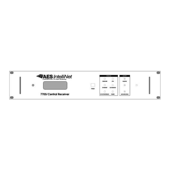
Page 10: Front Panel
3.1.1 LCD Display: The LCD is a 4-line display with 20 characters per line. It shows messages for the 7705i. Use this in conjunction with the Alert panel to interpret and acknowledge messages. There is also a tactile response sounder to provide audible confirmation of a successful button activation. - Page 11 This LED will turn off if CD turns off for 100 milliseconds. Power: Green Led - Indicates that proper power is detected at the monitored points within the 7705i. 3.1.4 Alert Panel: This section of the front panel contains an LED and two Push Button Switches.
-
Page 12: Rear Panel
Modem connection for IP-Link Transceivers that cannot communicate via the Internet or TCP/IP. When connecting the 7705i MultiNet Receiver’s modem to a telephone line, use only 26 AWG or larger wire. A UL Listed 497A Secondary Protector is required to be installed on the incoming lines. - Page 13 “Signaling use” under UL 864, such as an AES 75-0101. Appendix F for a listing of generated messages. Note: These are to be used for initial setup only and are not to remain connected. 40-7705I-UM Page 13 Rev 6a March 1, 2018...
-
Page 14: Installation And Setup
They may also be needed later for occasional configuration modifications. The 7705i, monitor and any network related equipment shall be connected to a suitable UL-UPS to maintain power during power outages. -
Page 15: Software Installation
AES equipment resides. 7705i must be installed in a UL Listed metal rack-mounting cabinet that complies with UL864. The cabinet must be provided with integral outlets and the ability to connect AC input via conduit. All wiring exiting the cabinet must be in electrical conduit. - Page 16 AES. TELCO Line Keyboard Mouse Monitor AC Power Y Cable Alarm Monitoring Default IP Address Port 1 = 192.168.0.101 See Appendix E for messages Default IP Address Port 2 = 10.0.1.221 40-7705I-UM Page 16 Rev 6a March 1, 2018...
- Page 17 UL 497B Surge Alarm Monitoring Protector See Appendix E for messages Default IP Address Port 1 = 192.168.0.101 SINGLE POINT GROUND TO 7705i .Not investigated by UL Default IP Address Port 2 = 10.0.1.221 40-7705I-UM Page 17 Rev 6a March 1, 2018...
- Page 18 Acquire IP Addresses UL Ethernet Hub from IT Dept. Off Site Remote Location Internet Head End - Location of 7705i MultiNet Receivers Acquire IP Address from IT Dept. Customer Provided 7705i Receiver as shown UL Ethernet Hub below. For redundancy.
-
Page 19: System Startup And Access
Switch the power of the 7705i to the on position. The main switch for the power supply is on the back panel. This must be switched to on first. Then if the startup process does not automatically begin, push the Power push button Switch on the front panel to initiate the startup process. -
Page 20: Power Down - Information
Power Down - Information: The power to the 7705i should not just be removed without going through the proper shut down procedure. DO NOT REMOVE POWER OR TURN OFF POWER of the 7705i MultiNet Receiver WITHOUT USING THE PROPER SHUT DOWN... -
Page 21: Linux Command Line
Connect to the 7705i using VNC Viewer or your workstation program as instructed by the person or persons responsible for your configuration. -
Page 22: The Gui Desktop And The Aes Menu
The menu available from the right click is also shown. This view is also a representation of what the screen would look like if you were to access it using VNC Viewer as your workstation program. Figure 5-2 GUI Desktop 40-7705I-UM Page 22 Rev 6a March 1, 2018... -
Page 23: Start The Terminal Program
Menu. The terminal window in the GUI desktop screen is shown below in Figure 5-3. This is also a view using VNC Viewer from a remote PC that has access to the MultiNet receiver. Figure 5-3 Terminal window on the MWM Desktop 40-7705I-UM Page 23 Rev 6a March 1, 2018... -
Page 24: Setting Time
Follow instructions and answer the questions presented on the screen. Contact AES Technical Support for additional information on adjusting the Time Zone on your MultiNet receiver. 40-7705I-UM Page 24 Rev 6a March 1, 2018... -
Page 25: Review Your Tcp/Ip Configuration
MultiNet system is being placed in a network that has existing MultiNet devices then these new devices need unique settings. Failure to do so will result in conflicts. 7705i Default Ethernet Port Settings Parameter Ethernet Port 1 / eth0... -
Page 26: Suggested Tcp/Ip Settings For Second Multinet Receiver
Failure to get the proper values could prevent proper operation of the MultiNet devices or other existing devices on the network. Second 7705i/ Suggested Ethernet Port Settings Parameter Ethernet Port 1 / eth0... - Page 27 For a simple installation where a crossover Ethernet cable is used to connect the 7170 IP-Link Transceiver directly to Ethernet Port 1 (J10), eth0 of a single or the first 7705i MultiNet Receiver, the following settings in this receiver along with the recommended settings in the 7170 manual should allow communication: Figure 4-1.
- Page 28 Once the editor is closed the script will continue by initializing the new settings and running a few tests. Watch the screen for errors. 40-7705I-UM Page 28 Rev 6a March 1, 2018...
-
Page 29: Testing Tcp/Ip Configuration
You should receive responses indicating how long the response took, if it failed or timed out. The example screen below shows the “ping –help” response, a successful ping and a failed ping. Figure 5-6 Example of a ping to a gateway PC 40-7705I-UM Page 29 Rev 6a March 1, 2018... -
Page 30: User Logout From Directly Attached Keyboard & Monitor
For example: If using VNC Viewer, close the program by clicking on the X in the upper right corner of the VNC window. The password will be required the next time you attempt access. 40-7705I-UM Page 30 Rev 6a March 1, 2018... -
Page 31: Admin Gui For Configuration And Administration
This will significantly reduce security, as anyone who gets access to the workstation may be able to modify your MultiNet Receiver Server settings. 40-7705I-UM Page 31 Rev 6a March 1, 2018... - Page 32 Below is a sample screen from the Admin GUI. The following sections describe the functions of the Administration program. Figure 6-2 Admin GUI program home screen 40-7705I-UM Page 32 Rev 6a March 1, 2018...
-
Page 33: Server Configuration
Linux and the hardware of this receiver, do not enter anything else here unless directed by AES Technical or Engineering Support. LCD Device Path: Unix path used by the LCD in your IP-Link Transceiver. Default is “/dev/ttyS2”. 40-7705I-UM Page 33 Rev 6a March 1, 2018... -
Page 34: Define Business Units: (You Must Have At Least One)
Do not select this checkbox if this is an additional Business Unit that will use the Serial Port already configured for use by another Business Unit. Figure 6-4 Add Business Unit Screen 40-7705I-UM Page 34 Rev 6a March 1, 2018... - Page 35 USDI – This data type is expecting data from a USDI Subscriber. Also creates Alarm data. o GPS – Do not select data type. o Vending – Do not select data type. o Pump – Do not select data type. 40-7705I-UM Page 35 Rev 6a March 1, 2018...
- Page 36 Once you have entered data in all the required fields, click If you have checked “Alarm Automation System?” you will see the screen shown on the next page. If you did not, this screen will be skipped. 40-7705I-UM Page 36 Rev 6a March 1, 2018...
-
Page 37: Add A Business Unit - Alarm Automation Settings
“Alarm Automation System?” checkbox. You will be presented with a data entry screen shown above. You can connect to the alarm monitoring system via serial connection and or TCP/IP connections. The following fields are available to edit. 40-7705I-UM Page 37 Rev 6a March 1, 2018... - Page 38 7705i Receiver. This shall be configured by UL1981 Central-Station Automation Systems Requirements. Entering a value of 0 disables the feature and the 7705i will not be looking for the heartbeat. The MultiNet Receiver will not annunciate a fault due to no heartbeat being sent.
- Page 39 Automation an additional widows of 20 seconds and two attempts to send the heartbeat before a fault message is generated by the 7705i Receiver. Default is 0 or disabled. This shall be configured by UL1981 Central-Station Automation Systems Requirements. o Automation Message Format: ...
- Page 40 Subscribers for this Business Unit. When complete click… The following screen, or one similar if Alarm Automation System were not checked should be presented. After reviewing the information, Click Add Business Unit to complete the process 40-7705I-UM Page 40 Rev 6a March 1, 2018...
- Page 41 Figure 6-7 Add a Business Unit - continued A partial view of the final screen indicating a successful add, is shown below. Figure 6-8 Add a Business Unit – completed 40-7705I-UM Page 41 Rev 6a March 1, 2018...
-
Page 42: Business Unit Overview
Business Units. You can select an underlined link, to view details. Figure 6-9 Business Unit Overview Below is a sample compressed screen that shows the details for the underlined link MySecurityOne. Figure 6-10 Business Unit Details 40-7705I-UM Page 42 Rev 6a March 1, 2018... -
Page 43: Modify A Business Unit
BU will produce a unique alarm message for each. This affects the receiver number in the string of characters sent to alarm automation. Figure 6-11 Modify Business Unit: 40-7705I-UM Page 43 Rev 6a March 1, 2018... -
Page 44: Subscriber Database Setup
You will first be prompted to select the Business Unit to assign the added Subscriber. Business Unit: Select from the pull down list. A different list from another example system is shown in this example. 40-7705I-UM Page 44 Rev 6a March 1, 2018... - Page 45 Unit Type: Select the unit type from the pull down list provided. If the unit type is not properly selected, certain operational functions, such as Zone Programming, may not work correctly. You may not be presented with the correct zone-programming window. 40-7705I-UM Page 45 Rev 6a March 1, 2018...
- Page 46 Figure 6-15 Add Subscriber Confirmation Screen When you successfully add a subscriber, you are given the option to add alarm data after adding the subscriber. Click to perform this step next. 40-7705I-UM Page 46 Rev 6a March 1, 2018...
-
Page 47: Alarm Data
Figure 6-16 accountAlias: If a non-zero number is entered into this field, the account number in the alarm event will be replaced by this number prior to delivery to the automation system. 40-7705I-UM Page 47 Rev 6a March 1, 2018... -
Page 48: Close Your Browser When Finished With Admin Gui
For the same reasons, do not leave untended, a workstation that has the Admin GUI Web pages open. Closing the browser will require the Admin GUI Password for a subsequent access attempt. 40-7705I-UM Page 48 Rev 6a March 1, 2018... -
Page 49: Workstation Access And Login
7.0 Workstation Access and Login: Once properly configured, the 7705i can be accessed by using programs running on a workstation. There are as usual multiple configurations and programs that will accomplish this task. As you have already experienced, password protected... -
Page 50: Installing Vnc Viewer
Right click on desktop and select new .. Shortcut … You can use the browse button to look for the file you saved Double click on the shortcut just created to run VNV Viewer. 40-7705I-UM Page 50 Rev 6a March 1, 2018... -
Page 51: Using Vnc Viewer
1 is peabody2. You should now be connected and be able to run programs as needed. An example of the screen you should see is in the next section. 40-7705I-UM Page 51 Rev 6a March 1, 2018... -
Page 52: After Login
If you are connecting for a user associated with a Business Unit you will have the Ipctrl program on the screen. Ipctrl is the interface you will use for managing Subscribers assigned to you. 40-7705I-UM Page 52 Rev 6a March 1, 2018... -
Page 53: Multinet Receiver Programs And Utilities
It restarts any program that is not running. 5- LCD is the program that controls the messages displayed on the LCD display located on the front panel on the 7705i MultiNet Receiver. 6- filedaemon is the program that handles the data sent to the printer. -
Page 54: Multinet Utility Programs And Scripts
This command with the status argument is used to get the status of the programs listed above. Use the following command to get the status of the MultiNet programs and determine if it is running: aesctrl status<Enter> 40-7705I-UM Page 54 Rev 6 May 8, 2017... - Page 55 5- editnetworketh0 – This script is used to modify the settings of Ethernet Port 1 (eth0). See Section 5.13 7- editnetworketh1 – This script is used to modify the settings of Ethernet Port 2 (eth1). See Section 5.13 40-7705I-UM Page 55 Rev 6 May 8, 2017...
-
Page 56: Special Purpose Circuits
Never continue to operate the MultiNet receiver when the Sounder is active and cannon be silenced. 40-7705I-UM Page 56 Rev 6 May 8, 2017... -
Page 57: Aes Menu In The Gui Desktop
On/Off switch to turn off the receiver. Damage to the file system may occur if not properly shut down. 12- Quit… - Use this function to quit using the MWM GUI and return to a command prompt. 40-7705I-UM Page 57 Rev 6 May 8, 2017... -
Page 58: Managing Users
If you are not in the root directory or to be sure you are type the following: cd /root<Enter> Or to view the from any other directory type the following command: cat /root /user_info<Enter> 40-7705I-UM Page 58 Rev 6 May 8, 2017... -
Page 59: Changing A User's Password
Using telephone numbers, birthdays and the like are not recommended and could be easier to guess leaving your system at risk. An example is something similar to: “Ax2zT78o”. 40-7705I-UM Page 59 Rev 6 May 8, 2017... -
Page 60: Change Admin Gui Access - Username And Password
Once restarted the new username and password should be in effect. Attempt to access the Admin GUI using the new username and password Deleting a User: This is managed by the deletion of the Business Unit within the Admin GUI. 40-7705I-UM Page 60 Rev 6 May 8, 2017... -
Page 61: Test New User Login
Business Unit you are testing. o Enter the password followed by <Enter> when prompted. o Once successful, confirmed with a prompt including the username you typed, you should logout again. Type logout <Enter> 40-7705I-UM Page 61 Rev 6 May 8, 2017... -
Page 62: Admin Gui Database Functions
Figure 10-2 Select Subscriber ID The next screen will provide the options to Modify Subscriber Configuration, Alarm Data or Delete Subscriber. By now you should have seen most of those screens. Figure 10-3 Data for Subscriber 40-7705I-UM Page 62 Rev 6 May 8, 2017... -
Page 63: Routing Table Screen
An example screen is shown below. When your system is new there may not be any information to display until signals are successfully received by an IP-Link Transceiver and passed on to the 7705i MultiNet Receiver. Figure 10-4 Routing Table... -
Page 64: Ip-Link Status Screen
Alarm data that is stored can also be viewed. The following screen, accessed by selecting SysOp / Alarms, lets you select the specifics about the alarm data you wish to view. Figure 10-7 Get Alarm data, (Signal History) request screen 40-7705I-UM Page 64 Rev 6 May 8, 2017... -
Page 65: Close Your Browser When Finished With Admin Gui
For the same reasons, do not leave untended, a workstation that has the Admin GUI Web pages open. Closing the browser will require the Admin GUI Password for a subsequent access attempt. 40-7705I-UM Page 65 Rev 6 May 8, 2017... -
Page 66: Iplinkctrl (Ipctrl) Network Management Software
RF signals in real time, IPCtrl displays data packets that are delivered by a 7170 IP-Link transceiver. Following is an example of the IPCtrl screen. Figure 11-1 Sample screen from the IPCtrl program 40-7705I-UM Page 66 Rev 6 May 8, 2017... -
Page 67: Ipctrl Function Groups
Hot keys will only execute the associated function when the pull downs are closed. • Activate any other function group by clicking on the function group name in the Menu bar. 40-7705I-UM Page 67 Rev 6 May 8, 2017... -
Page 68: Using The Pick List Pop Up To Select A Subscriber Id
The “last” route, or most recent route, is the default setting on this popup. To select the second most recent route, select the most recent route, and the same for the most frequent route. 40-7705I-UM Page 68 Rev 6 May 8, 2017... -
Page 69: The Message Function Group
Press <M> or click on Message in the menu bar. The pop-up illustrated above will appear. Use the arrow keys to highlight a message function and press <Enter> to select it. Proceed by selecting your target unit and choosing a route of communication. 40-7705I-UM Page 69 Rev 6 May 8, 2017... - Page 70 • Press <ALT>+<M>, then <7> Zone Configuration database. The Zone or Press <ALT>+<Z> Configuration is part of the Programming • Select Target Unit Function Group described in the following • Select Route pages. 40-7705I-UM Page 70 Rev 6 May 8, 2017...
-
Page 71: Control Function Group
The pop-up illustrated above will appear. Use the arrow keys to highlight a control function and press <Enter> to select it. Proceed by selecting your target unit and choosing a route of communication. 40-7705I-UM Page 71 Rev 6 May 8, 2017... - Page 72 • To confirm the function, perform a "Get Subscriber Mode Data" to retrieve the current status of this mode (Message group, # 9) and to update the database. • Refer to subscriber unit and IntelliTap manuals for more information. 40-7705I-UM Page 72 Rev 6 May 8, 2017...
- Page 73 • Select Route of this mode (Message group, # 9) • Enter D to Disable, E to • Refer to 7450 or 7440 subscriber unit manuals for more Enable Line Cut Monitoring information. 40-7705I-UM Page 73 Rev 6 May 8, 2017...
-
Page 74: Programming Function Group
Subscriber unit using the IPCtrl software. When the programming window appears, the fields will usually be pre-filled with values. If there is a database entry for the selected Subscriber, the values 40-7705I-UM Page 74 Rev 6 May 8, 2017... - Page 75 10 seconds. To change the event report delay, enter the new value and press <Tab> to move to the next field. A delay of less than 10 seconds is not recommended. 40-7705I-UM Page 75 Rev 6 May 8, 2017...
- Page 76 (Refer to subscriber manuals.) NOTE: For all remote program functions, watch to make sure that a data confirmation packet is received from the target subscriber (watch scrolling message screen area). 40-7705I-UM Page 76 Rev 6 May 8, 2017...
- Page 77 • The TTL time is included in packets generated by TTL capable Subscribers. This feature is available in Subscribers with firmware Version 2.1 and later which was first released in late 2000. 40-7705I-UM Page 77 Rev 6 May 8, 2017...
- Page 78 To confirm the data, press <Alt>+<N> to query the subscriber for Packet Life settings. When the TTL parameters packet has been received back, check this screen again. See - Get Packet Life Settings, Message Functions Group 40-7705I-UM Page 78 Rev 6 May 8, 2017...
- Page 79 Figure 11-15 Relay Control Menu Choose a number: 0 for Off, 1 for On or 2 for Toggle / Momentary and select [OK] to control Relays in a Subscriber equipped with appropriate module. 40-7705I-UM Page 79 Rev 6 May 8, 2017...
- Page 80 Otherwise click No for alarm message to be reported on a short or open. A raised appearing button indicates the default or current programming, if it is stored in the database from a 40-7705I-UM Page 80 Rev 6 May 8, 2017...
- Page 81 The numbers below the restoral row selects the bank. Scroll through the numbers using the arrows and then click the number to select that bank. The information in the window will change representing those zones. 40-7705I-UM Page 81 Rev 6 May 8, 2017...
- Page 82 N.O. W/Restoral – AC Fail (from 7072 multi-board) Zone 8: Refer to Subscriber Unit Manual for details on zone wiring and programming. Zone Configuration window for the 7050E Rev 1.8 and older Figure 11-19 40-7705I-UM Page 82 Rev 6 May 8, 2017...
- Page 83 Code to be sent to the Alarm Monitoring System for each of the 8 zones. The former standard produced only an E140, which is typically listed as a General Alarm. Select normal to have an E140 sent to alarm monitoring. Zone Configuration window for the 7450/7440 Figure 11-21 40-7705I-UM Page 83 Rev 6 May 8, 2017...
- Page 84 This screen below appears if the unit zone information is in the database. Figure 11-22 The Zone configuration pop-up window offers the following options for the programming of each alarm zone. Supervised Fire Restoral with Supervised or Fire Bypassed 40-7705I-UM Page 84 Rev 6 May 8, 2017...
- Page 85 Figure 11-23 Automatic Test Supervision Select On or Off radio button to configure this function. Note: Enabling supervision function suppresses Check-In messages from being sent to automation. Only exceptions are reported. 40-7705I-UM Page 85 Rev 6 May 8, 2017...
-
Page 86: Data Radio Function Group
Print is selected. Figure 11-25 It Displays the routing record and current status of the selected Subscriber unit. All UL Burglar Alarm and Commercial Fire Alarm Systems require a minimum of 2 paths. 40-7705I-UM Page 86 Rev 6 May 8, 2017... - Page 87 Same View as above except that the information is sent to • Press <ALT> + <P> the printer instead of the screen. • Press <R> • Select Target Unit • View available data View Paths/Thru window: Figure 11-26 40-7705I-UM Page 87 Rev 6 May 8, 2017...
- Page 88 Select or Enter the Origin ID. Then enter the ID of the unit data is to be forwarded to. Add a memo (such as name/address) of up to 40 characters. This memo is sent with all forwarded data. 40-7705I-UM Page 88 Rev 6 May 8, 2017...
- Page 89 - r 7050 version prior to 2 the relay is toggled. Be aware that you cannot be sure if the relay will be left open or closed. Only that it will change state at least once. 40-7705I-UM Page 89 Rev 6 May 8, 2017...
-
Page 90: System Function Group
(For more information, see the section on Database Group / Edit Radio Forward Table.) A pop up window shows you the current status global forwarding (On or Off). Enter Y/yes or N/no to change the status. 40-7705I-UM Page 90 Rev 6 May 8, 2017... -
Page 91: Interpreting Screen Messages
The type of routing used is LNRT This is an Alarm message. It is displayed in red for easy recognition The 7 bytes of data indicate new alarm on the Subscriber’s Zone 1 40-7705I-UM Page 91 Rev 6 May 8, 2017... -
Page 92: Operation
Automatic operation of the MultiNet receiver is a mode where alarm and other messages are being sent to an Alarm Monitoring System. No user interaction is required at the Receiver as long as the Alarm Monitoring System properly acknowledges the messages. 40-7705I-UM Page 92 Rev 6 May 8, 2017... -
Page 93: Warranty And Service Procedure
13.0 Warranty and Service Procedure: AES CORPORATION LIMITED PRODUCT WARRANTY AND TECHNOLOGY LICENSE LIMITED PRODUCT WARRANTY: AES warrants to the original purchaser that the AES Subscriber Unit will be free from defects in material and workmanship under normal use and service for three (3) years from the date of original purchaser's purchase. Except as required by law, this Limited Warranty is only made to the original purchaser and may not be transferred to any third party. -
Page 94: Appendices
APPENDICES 40-7705I-UM Page 94 Rev 6 May 8, 2017... -
Page 95: Appendix A Common Linux Commands
To set the time zone where the MultiNet receiver is located. 40-7705I-UM Page 95 Rev 6 May 8, 2017... -
Page 96: Appendix B Server-Generated Lcd Display Messages
Server-generated LCD Display Messages. Top line description: The LCD is a 4-line display with 20 characters per line. It shows messages for the 7705i. Use this in conjunction with the Alert panel to interpret and acknowledge messages. There is also a tactile response sounder to provide audible confirmation of successful button activation. - Page 97 LCD screen until the operator corrects the failure. When the server detects the correction it will turn off the LED for that failure and remove the associated message from the LCD display. 40-7705I-UM Page 97 Rev 6 May 8, 2017...
-
Page 98: Appendix C Software Installation Instructions
7170 IP-Link Transceiver. Part Number: 40-7705I-IS Title: AES 7705i MultiNet Receiver System – Initial Installation and Setup Guide This Installation and Setup Guide provides instruction for installing and setting up the MultiNet system including the 7705i / and the 7170 IP-Link Transceiver. -
Page 99: Appendix D Sharing The Serial Port With Additional Business Units
7. To close the file and exit the utility type the following character combination: <Ctrl> + C 8. At the command prompt of the Konsole terminal, enter the following command: chmod 777 ipctrl.(secondBU).cfg<Enter> 40-7705I-UM Page 99 Rev 6 May 8, 2017... - Page 100 13. Create alarm signals using a Subscriber in the additional Business Unit and confirm proper delivery to Alarm Automation. 14. If there are any other Business Units they should be tested as well. 40-7705I-UM Page 100 Rev 6 May 8, 2017...
-
Page 101: Appendix E Alarm Output Codes Produced By The Multinet Receiver
= 00 for AES signals. As received for IntelliTap. Group or partition = C for AES signals. As received for others. U = user. = Zone/contact ID, Status or Fault code = Single <Blank space> <CR> = Carriage return code. 40-7705I-UM Page 101 Rev 6 May 8, 2017... - Page 102 Zone Trouble. (Zone/contact ID = 001 to 008) Protection Loop 7744 Battery Charger Trouble (Zone/contact ID = 009) Protection Loop 7744 Ground Fault (Zone/contact ID = 010) Periodic test report Automatic Supervisory Check-In 40-7705I-UM Page 102 Rev 6 May 8, 2017...
- Page 103 Note that this is a restore signal and may not cause an alert. Look in log files. REC# = MultiNet Receiver ID IPL# = IP-Link ID ACCT = Subscriber ID n or nn = variable number, rang as specified 40-7705I-UM Page 103 Rev 6 May 8, 2017...
- Page 104 R1 REC# 18 R357 00 C916 IP-Link antenna restored. Zone/contact ID = 916 REC# = MultiNet Receiver ID IPL# = IP-Link ID ACCT = Subscriber ID n or nn = variable number, rang as specified 40-7705I-UM Page 104 Rev 6 May 8, 2017...
- Page 105 In Ademco mode the receiver will respond to 3 inputs or signals from the monitoring system. receiver reply will be - <LF>00sOKAYs@<CR> <0x06> or ASCII code 6 receiver considers last message acknowledged <0x15> or ASCII code 21 receiver will re-send last message (if not acknowledged) 40-7705I-UM Page 105 Rev 6 May 8, 2017...
- Page 106 It will never be greater than decimal 15. The number in position N2 represent the decimal equivalent of a Hexadecimal number where 1 = decimal 16 and 2 = decimal 32. 40-7705I-UM Page 106 Rev 6 May 8, 2017...
- Page 107 Zone Trouble Signal. Zone NNN ٭ 10R1 ACCT T nnn T NNN ST NNN Prior Zone Trouble zone NNN ٭Input still active. Reported during Status Request or Check-In 10R1 ACCTST nnn 40-7705I-UM Page 107 Rev 6 May 8, 2017...
- Page 108 IPL# X 814 X 814 “7030, Transceiver Enclosure Voltage Restore” 10R1 IPL# X 815 X 815 “LCD offline” 10R1 REC# X 911 X 911 “LCD online/restore” 10R1 REC# X 912 X 912 40-7705I-UM Page 108 Rev 6 May 8, 2017...
- Page 109 SY 3XX where 3XX is a copy of the event code Event Codes with numbers E4XX will be reported as: O NNN where NNN is the Point ID or Contact ID number 40-7705I-UM Page 109 Rev 6 May 8, 2017...
- Page 110 In mode 1 the AES receiver will respond to two inputs or signals from the monitoring system. <0x06> receiver considers last message acknowledged <0x15> receiver will re-send last message (if not acknowledged) Other Messages: 301ssAESs7000sVX.XXs<0x14> X.XX this reports the version number of the firmware 40-7705I-UM Page 110 Rev 6 May 8, 2017...
-
Page 111: Appendix F Printer Messages Produced By The Multinet Receiver
Manual Acknowledge (Tracking=21924) -> 11 9371 18 A140 00 C006 -- Alarm Automation System is up! (serial) -- IPL 1111 Battery Voltage - Fault Alarm codes printed are defined in Appendix E 40-7705I-UM Page 111 Rev 6 May 8, 2017...
Need help?
Do you have a question about the 7705i and is the answer not in the manual?
Questions and answers