
Related Manuals for Marshall Electronics VS-102 HDSDI/HDI


Summary of Contents for Marshall Electronics VS-102 HDSDI/HDI
- Page 1 Marshall Electronics VS‐102‐ HDSDI / HDI HD Video Server H.264 Encoder / Decoder User Manual ...
- Page 2 Product options and specifications can be changed without notice. The information in this manual is furnished for informational use only and should not be construed as a commitment by Marshall Electronics, Inc. Marshall Electronics, Inc. assumes no responsibility or liability for any errors or inaccuracies that may appear in this publication.
-
Page 3: Table Of Contents
1- Introduction ___________________________________________________________________________ 1 - Introduction..........................4 1.1 About this Manual ......................4 1.2 Features ........................4 1.3 Product and Accessories ....................5 1.4 System Connections.....................8 2 - Installation ........................... 11 2.1 Connecting Video ....................... 11 2.2 Connecting Audio ....................... 11 2.3 Connecting Serial Ports .................... -
Page 4: Introduction
1- Introduction ___________________________________________________________________________ 1.1 About this Manual This User Manual provides information on installation setup, operation of the video server, as well as troubleshooting tips. 1.2 Features Video Server is a video and audio transmission system that provides broadcast quality audio and video, based on IP network through LAN, ADSL/VDSL, and wireless LAN. -
Page 5: Product And Accessories
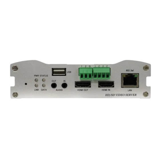
1- Introduction ___________________________________________________________________________ Connection to internal or external USB storage for remote access, recording and playback User Interface Diagnose and upgrade through dedicated program called VS Manager System Configuration using Internet Explorer High Reliability Reliable Embedded System ... - Page 6 1- Introduction ___________________________________________________________________________ Part Names and Functions Front View ⑩ ② ④ ⑤ ⑨ ⑧ ⑥ ③ ⑦ ① Parts Function Display System Status Audio Input Audio Input Audio Output Audio Output HDMI Input HDMI Video Input HDMI Output HDMI Video Output USB Port USB 2.0 100/10-Base-T Ethernet...
- Page 7 1- Introduction ___________________________________________________________________________ Rear View Part Function Power DC +12V Power Input RS-422/485 Serial Port for PTZ Control RS-232 Serial Port for PTZ Control Composite In/ Composite Video Input / Output Output HD/SD-SDI HD/SD-SDI Video Input / Output In/Output* HD/SD-SDI Output is optional User Manual VS-102 HDSD/HDI - V2.3 Page 7 of 64 5/7/12...
-
Page 8: System Connections
1- Introduction ___________________________________________________________________________ 1.4 System Connections Video Server operates as one of two modes; Encoder or Decoder. Video Server Systems can be connected in either 1-to-1 where one encoder is connected to one decoder or 1-to-multiple where one encoder connected to many decoders. The following chart shows status of video, audio and serial data on each mode: System Mode Video... - Page 9 1- Introduction ___________________________________________________________________________ 1:N Connection (Uni-Directional Transmission) Remote Center Site Decoder Encoder Decoder Decoder In this configuration, a site can be monitored from many remote center locations. Maximum connections would be limited by the network bandwidth. Functionally, the VMS (Video Management System) software can replace the decoder.
- Page 10 1- Introduction ___________________________________________________________________________ VMS (Video Management System) Site Remote Center Encoder Site Remote Center Encoder Decoder VMS (Video Management System) is a Windows based remote monitoring program to access multiple encoders for real-time monitoring or control of the encoders and connected cameras.
-
Page 11: Installation
2- Installation ___________________________________________________________________________ 2.1 Connecting Video Encoder System Connect camera video output line to the encoder (video server) video input port. Connecting with Megapixel Camera Connect a camera which supports HDMI or HD-SDI output to the HDMI or HD-SDI Input port of video server accordingly. -
Page 12: Check If It Works
2- Installation ___________________________________________________________________________ 2.6 Check If It Works Once the power is supplied to the camera, it will start booting. The system will boot up to operating mode after approximately 40-60 seconds. The green LED on the Ethernet Port will flash indicating the system is ready. Software provided on the disc called VS Manager allows you to check the IP address and other network details of the camera. -
Page 13: Remote Video Monitoring
2- Installation ___________________________________________________________________________ Description of LED System Status can be monitored with the LED Display: State Description Power OFF Power ON Green Blinking Normal Operation System Failure: Needs Diagnostics Constant Change NTSC/PAL setting does not between Red and match with Input Video Signal Green Red Blinking Failed to obtain IP Address in... -
Page 14: System Operation
3- System Operation __________________________________________________________________________ 3.1 Remote Video Monitoring There are two ways to monitor video when the Center System and Video Server are connected. In order for a proper operation, an IP Address must be set accordingly. Please refer to the VS Manager Manual enclosed with product for further details. Default ID: admin Default Password: 1234 Video Monitoring with Decoder System... - Page 15 3- System Operation __________________________________________________________________________ Video Select Select the Video Stream to be viewed: Primary or Secondary This camera is capable of Dual Streaming; Primary Streaming and Secondary Streaming. Video will be displayed according to the resolution set on video configuration.
- Page 16 3- System Operation __________________________________________________________________________ Alarm Output Operate the Alarm Device by pressing the number icon. This camera supports One Alarm Output. A number icon indicates the status of the alarm device. Snapshot Capture Video Images and save them as BMP or JPEG files. ...
-
Page 17: Initialization Of Ip Address
3- System Operation __________________________________________________________________________ 3.2 Initialization of IP address If a System IP Address is lost, the system can be reset to the System Default IP Address using the Reset Button in the back side of the system. 1. While system is in operation, press the reset button for more than 5 seconds. 2. - Page 18 4- Remote Configuration ___________________________________________________________________________ Remote Setting is available by using Web Browser. Enter IP Address of the Camera and a live view screen appears (see below). Press the Setup button located in the upper right area of the monitoring screen for Server Setup. For Remote Setting, the user should have manager level authority or higher.
-
Page 19: Remote Configuration
4- Remote Configuration ___________________________________________________________________________ 4.1 System Configuration User Manual VS-102 HDSD/HDI - V2.3 Page 19 of 64 5/7/12... - Page 20 4- Remote Configuration ___________________________________________________________________________ General System ID Enter System ID which is used as the Camera Title Name. The set System ID is displayed with Video Image on the Web Browser. The System ID is also transferred to and displayed on the remote software, such as VMS. ...
- Page 21 4- Remote Configuration ___________________________________________________________________________ Restore Stored configuration can be browsed and restored. The server is rebooted once the Config Restore Button is pressed. Time Start Time The most recent Camera Booting Date and Time. Current Time Enter a New Date and Time and press the Set Current Time Button to update. ...
-
Page 22: Video Configuration
4- Remote Configuration ___________________________________________________________________________ 4.2 Video Configuration User Manual VS-102 HDSD/HDI - V2.3 Page 22 of 64 5/7/12... - Page 23 4- Remote Configuration ___________________________________________________________________________ Encode Enable Preview 1. Select ON to enable to Display Video on the monitor that is connected to the Composite or HD-SDI Video Port. 2. Select the Output Format according to the end of the Video Page. When Enable Preview is ON, Dual Streaming is not available.
- Page 24 4- Remote Configuration ___________________________________________________________________________ Bit Rate Determine Bit Rate value between 32 ~ 10240kbps. Bit Rate Mode (CBR Encoding) allows you to set a Fixed Target Bit Rate that consumes a predictable amount of Bandwidth. In order to stay within the Bit Rate limit, Video Quality is controlled dynamically according to the complexity or activity changes in the Input Video.
- Page 25 4- Remote Configuration ___________________________________________________________________________ Motion Detection Area Editing Configure regions to apply motion detection. Regions of arbitrary shape can be configured by the following steps: Select Enable in the Edit Menu. In the Mode Menu, select Set to include cells in the motion detection region and select Erase to excluding them.
- Page 26 4- Remote Configuration ___________________________________________________________________________ Burn In OSD Insert System ID and Date/Time in the Compressed Video. System ID and Time respectively can be turned on or off in the video. Position and Font size can be configured also. System ID for Burn In OSD exists independently from the Normal System ID.
-
Page 27: Audio Configuration
4- Remote Configuration ___________________________________________________________________________ 4.3 Audio Configuration Algorithm Algorithm Select the Audio Algorithm: G.711 or AAC. G.711 and AAC supports client to server side direction. Bi-directional audio communication is supported as well. Bit Rate Select the Bit Rate between 64Kbps and 128kbps when AAC is selected. Sampling Rate is fixed at 8KHz and 32KHz for G.711 and AAC respectively. - Page 28 4- Remote Configuration ___________________________________________________________________________ Input Gain Set Audio Input Gain from 0 to 31. Audio Output Configure the Audio Source to be played on Audio Output Port. Decoded Audio: Audio Stream from client is played. Loopback: Audio Data from the Audio Input Port is looped back to the Audio Output Port.
-
Page 29: Network Configuration
4- Remote Configuration ___________________________________________________________________________ 4.4 Network Configuration User Manual VS-102 HDSD/HDI - V2.3 Page 29 of 64 5/7/12... - Page 30 4- Remote Configuration ___________________________________________________________________________ Local IP Mode Select the IP Mode: Fixed IP or DHCP (Dynamic Host Configuration Protocol). Depending on the selected mode, further configuration is provided below: IP Mode Selection Description Local IP Fixed IP Address Fixed IP Local Gateway Gateway IP Address Local Subnet...
- Page 31 4- Remote Configuration ___________________________________________________________________________ Ipv6 Ipv6 Address Enter the designated Ipv6 Address. Ipv6 Subnet Prefix Length Enter the bit number of Ipv6 Subnet. Ipv6 Default Gateway Enter the designated Ipv6 Gateway. Ipv6 Link Local Display Ipv6 Link Local. Port ...
- Page 32 4- Remote Configuration ___________________________________________________________________________ Authentication RTSP Authentication If RTSP Authentication is ON, user in the client side is asked to enter User ID and Password. HTTP API Authentication When HTTP API authentication is ON, HTTP Authentication is asked for all clients that use HTTP API.
- Page 33 4- Remote Configuration ___________________________________________________________________________ MPEG-TS is a standard format for transmission and storage of audio, video, and data, and is used in broadcast systems such as DVB and ATSC. Transport Stream is specified in MPEG-2 Part 1, Systems (formally known as ISO/IEC standard 13818-1 or ITU-T Rec.
- Page 34 4- Remote Configuration ___________________________________________________________________________ Multicast Multicast IP The Multicast Menu is used for configuring the Multicast IP Address where media stream is delivered when a client’s Decoder, VMS or NVR software is connected in Multicast Mode. The Multicast IP Address selection range is between 224.0.0.0 and 239.255.255.255 and can only be used when Media Protocol is set to Multicast.
- Page 35 4- Remote Configuration ___________________________________________________________________________ Bit Rate Control When one or more clients are connected to the camera, some of the clients do not have enough bandwidth to receive the encoded stream completely. In this case, it is possible to select the stream video mode: Frame Drop Mode: Encoding is performed strictly according to video settings.
-
Page 36: Serial Configuration
4- Remote Configuration ___________________________________________________________________________ 4.5 Serial Configuration User Manual VS-102 HDSD/HDI - V2.3 Page 36 of 64 5/7/12... - Page 37 4- Remote Configuration ___________________________________________________________________________ Serial Port Configuration Serial Protocol: Two Serial Ports are on the Video Server: RS-232 & RS-422/485. (For the RS-422/485 Port, select RS-422 or RS-485). Serial Port Configuration: The Serial Ports can be configured with the following options: Mode Selection...
- Page 38 4- Remote Configuration ___________________________________________________________________________ Sensor Schedule Choose Sensor OFF or Sensor ON and click the cells to make Sensor Schedule according to day of the week and hour. Click desired “Cell” to set schedule. Click desired “Time Line” or “Date Line” to set schedule. To set cells in the schedule, click on “Empty Cells”...
- Page 39 4- Remote Configuration ___________________________________________________________________________ 4.6 Serial Configuration User Manual VS-102 HDSD/HDI - V2.3 Page 39 of 64 5/7/12...
-
Page 40: Event Configuration
4- Remote Configuration ___________________________________________________________________________ This server has Two Sensor Ports and Two Alarm Ports. When a decoder is connected to the server, instead of a PC client, one system becomes a Local System and the other becomes a Remote System. Actions can be configured for events from the Remote System as well as for the Local System. - Page 41 4- Remote Configuration ___________________________________________________________________________ Email Notification Specify the information to send when email is selected as an Event Action. Server Address: Enter email (SMTP) server address. Port: Specify a port for SMTP operation. Port 25 is the default port in SMTP operation.
- Page 42 4- Remote Configuration ___________________________________________________________________________ Message Description Email Sent Test email has been sent successfully. Reception Successfully can be checked with client. Connection to the SMTP server failed. It is Failed Connection necessary to check if the server is reachable and to SMTP Server server address and port are correct.
- Page 43 4- Remote Configuration ___________________________________________________________________________ FTP Base Directory: Specify the name of the directory to be created in the FTP server. It is valid only when Use Record is set to Use FTP on Record Session. Upload Video: Primary Video and Secondary Video (H.264 only), JPEG Capture can be selected for uploading.
-
Page 44: Preset Configuration
4- Remote Configuration ___________________________________________________________________________ 4.7 Preset Configuration (When configuring a Marshall IP Camera or using the IP Camera as a Video Source) Preset Select preset # and insert the name of preset. Set camera position for the preset and press Save List button. User Manual VS-102 HDSD/HDI - V2.3 Page 44 of 64 5/7/12... -
Page 45: Record Configuration
4- Remote Configuration ___________________________________________________________________________ 4.8 Record Configuration User Manual VS-102 HDSD/HDI - V2.3 Page 45 of 64 5/7/12... - Page 46 4- Remote Configuration ___________________________________________________________________________ DISK SD memory can be used; at least 1GB size is recommended. Options are EXT3 or FAT32 file system. A disk with either EXT3 or FAT32 file system can be read in Linux PC. However, only disk with FAT32 file system can be read in Windows PC. Less than 4Mbps of video bit rate is recommended when you record and monitor video simultaneously since frame dropping may happen due to performance limitation.
- Page 47 4- Remote Configuration ___________________________________________________________________________ Refer to the Chart for Checking Disk Status: Disk Status Description Disk Error Error Detected No Disk Disk is not connected to the system. Searching Disk Checking the status of disk. Refresh the information page and wait until the status is changed. Mounting and Performing recovery process when disk damage is found.
- Page 48 4- Remote Configuration ___________________________________________________________________________ Overwrite When the disk becomes full, the oldest data are deleted automatically. It is valid only when Use Record is set to Use Disk. Max File Size/Max File Length Max File Size option is for limiting the size of AVI file. If small file size is set, files of small size will be generated but numbers of the files will be increased.
- Page 49 4- Remote Configuration ___________________________________________________________________________ Schedule Table Actual Recording Mode is determined by Schedule Table where recording mode is configured by day (of a week) and hour. Operation of each Recording Mode as follows: Record OFF: No recording. Continuous: Records continuously. Disconnect: Recording is started when the system loses the connection to its last client (Decoder, VMS/NVR) etc.
- Page 50 4- Remote Configuration ___________________________________________________________________________ 4. Press Root to move back to the page with date list. Playback 1. Selecting an AVI file will show a dialog for opening or saving the file 2. Pressing Save button, the file will be stored in the PC. The AVI file can be played with Windows Media Player.
- Page 51 4- Remote Configuration ___________________________________________________________________________ 3. If you press Open in the dialog, the file will be downloaded and played automatically with Media Player. 4. Another connection through web is disabled during downloading and it is also not allowed to download two AVI files at the same time. ...
-
Page 52: User Configuration
4- Remote Configuration ___________________________________________________________________________ 4.9 User Configuration User List User can be registered and privilege level user can be specified. Admin User can set User Configurations. Max of 16 Users can be registered and each user can have one of four privileges. Privilege Allowed Operations Remarks... - Page 53 4- Remote Configuration ___________________________________________________________________________ Delete User Select the User to be deleted and press Delete button. Change Password Press Modify Password button. The following window will appear: Enter the current password and then set a new password. Modify Privilege Level Press Modify Privilege button to change User level.
-
Page 54: Decoder Configuration
5- Decoder Configuration ___________________________________________________________________________ Decoder Configuration is slightly different from Encoder Configuration. Different configurations for the encoder will be explained in Decoder Configuration. 5.1 System Configuration User Manual VS-102 HDSD/HDI - V2.3 Page 54 of 64 5/7/12... -
Page 55: Video Configuration
5- Decoder Configuration ___________________________________________________________________________ 5.2 Video Configuration Output Format Regardless of Input Resolution on Encoder or IP Camera, Decoder System of Video Server can display Video Format. Buffering You can store maximum 30 decoded frames temporarily by using buffering before displaying the frames. -
Page 56: Network Configuration
5- Decoder Configuration ___________________________________________________________________________ 5.3 Network Configuration Network page of Decoder has a section for specifying the remote system to connect and the other functions are same as Network Configuration of Encoder. User Manual VS-102 HDSD/HDI - V2.3 Page 56 of 64 5/7/12... - Page 57 5- Decoder Configuration ___________________________________________________________________________ Remote Type Normal: Connection for Marshall Encoder and Decoder. RTSP/RTP: Decoder system can make connection though RTSP protocol and get the stream via RTP. It is also possible to make connection with other vendor’s H.264 IP camera supporting standard RTSP/RTP and standard H.264 algorithm. To make RTSP Connection, set Remote Type to “RTSP”, enter the RTSP URL of remote system to Remote Address, and RTSP access port number to Remote Port.
-
Page 58: Event Configuration
5- Decoder Configuration ___________________________________________________________________________ 5.4 Event Configuration The Event Configuration configures the actions for each event type. Local section configures the actions for events from local (self=decoder) system, and configuration activates local devices and Remote sections configures the actions for events from Remote (Encoder or IP Camera) System. - Page 59 5- Decoder Configuration ___________________________________________________________________________ Sensor1 / Sensor2 Configure the actions when the sensor 1 or 2 is activated. Multiple actions can be set for a single event. On Video Loss Configure the actions when video input signal is lost. Multiple actions can be set for a single event.
-
Page 60: Display Configuration
5- Decoder Configuration ___________________________________________________________________________ 5.5 Display Configuration Disconnection Decoder system’s output mode on disconnected state can be configured. Freeze: Video image of the last frame is shown when there is disconnection. Black Screen: Black Screen is shown when there is disconnection. ... -
Page 61: Vs Manager
6- VS Manager ___________________________________________________________________________ VS Manager is a program used for basic configuration, diagnostics and firmware upgrade of video servers or IP cameras. VS Manager provides the following features: Finding Servers on the LAN and assigning IP Addresses. Monitoring Server Status: Encoding/Decoding, Serial, Sensor, etc. ... -
Page 62: Appendix
7- Appendix ___________________________________________________________________________ Appendix A: Sensor and Alarm Port Sensor Port Terminal Type Voltage Rating: 150VAC Current Rating : 2A Color : Red Sensor Signal Input Type NO Contact Signals Connection to External Device Alarm Port Terminal Type Voltage Rating: 150VAC Current Rating : 2A... - Page 63 7- Appendix ___________________________________________________________________________ Appendix B: Serial Port RS-232 Port Terminal Type 3 PIN Pin Arrangement Pin Description: Pin NO Pin Name Description RS232 TX(Transmit) RS232 RX(Receive) Ground RS-422/485 Port Port Type 4 PIN Pin Diagram Pin Description: Pin No. Pin Name Description RS422 RX-...
- Page 64 ___________________________________________________________________________ Marshall Electronics, Inc. 1910 East Maple Ave. El Segundo, CA 90245 Tel: (800) 800-6608 / (310) 333-0606 Fax (310) 333-0688 www.LCDRacks.com sales@lcdracks.com User Manual VS-102 HDSD/HDI - V2.3 Page 64 of 64 5/7/12...
Need help?
Do you have a question about the VS-102 HDSDI/HDI and is the answer not in the manual?
Questions and answers