Table of Contents
Advertisement
Advertisement
Table of Contents

Subscribe to Our Youtube Channel
Related Manuals for Singer 321C


Summary of Contents for Singer 321C
-
Page 2: Instruction Manual
Overlock Machine 131M-04 243M-24 / TF 132M-015 244M-24 133M-04 / TF 251M-35 134M-04 251M-55 241M-24 / 25 251H-56 ® Singer is a registered trademark of The Singer Company Limited or its affiliated companies. © 2009 Copyright The Singer Company Limited... -
Page 3: Table Of Contents
Contents 1 Safety Instructions Important Safety Instructions Safe Operation 2 Product Description and Machine Specification Product Description Machine Specification Motor, Motor Pulley and Belt 3 Mounting and Adjustment Instructions Table Cut-Out Diagram Machine Installation Lubrification and Oil Drainage Needle Attachment (or Replacement) Machine Threading Thread Tension Adjustment 3.6.1... - Page 4 Contents 6 Parts List Frame Components Cloth Plate Components Cover Components Main Shaft Components Needle Bar Components Thread Guide Components Upper Looper Components Lower Looper Components Front Looper Components 6.10 Cam Components 6.11 Differential Feed Components 6.12 Feed Dog Components 6.13 Trimming Components 6.14...
-
Page 5: Safety Instructions
• When the machine is in main- following items. cations of use should be followed. tenance. Read all instructions, Singer will not be held responsible • When the operator is not run- take care of this for any damage caused by unau- ning the machine. -
Page 6: Safe Operation
• To avoid the risk of electric shock, • To avoid accidents in case of a do not open the motor wiring box sudden start of the machine al- and do not touch the components ways turn it off when laying it Safe Operation assembled inside the wiring box. -
Page 7: Product Description And Machine Specification
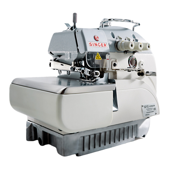
Product Description and Machine Specification High Speed Overlock Machine Product Description High Speed Overlock Machine Instructions Manual and Parts List... -
Page 8: Machine Specification
Model Needle Thread Gauge Stitch Stitch Differential Presser Needle Speed Usage [mm] width Length Height Singer Type [spm] 321C [mm] [mm] [mm] 131M-04 6120-06 75/11 6,000 Three-thread overlock machine Three-thread handkerchief edging 132M-015 6120-06 65/9 6,000 (rolled hem) overlock machine 0.7~2.0... -
Page 9: Mounting And Adjustment Instructions
Mounting and Adjustment Instructions Table Cut-Out Diagram Figure 1 High Speed Overlock Machine Instructions Manual and Parts List... -
Page 10: Machine Installation
Install the machine support compo- the needle bed surface to the table nents and the residues cam as indi- top is 100mm. For inserted assem- cated on figure 2. In case of semi-in- bly the distance is about 5.0mm. Machine serted assembly the distance from Installation Figure 2... - Page 11 Set the machine head on the sup- Install the friction motor pedal at the right side and the pedal of the port base. presser lifter at the left side. Connect the machine wheel to the Machine motor with the belt. Be sure the motor is clockwise di- Installation rected, referred to figure 3.
-
Page 12: Lubrification And Oil Drainage
Remove the oil flow sight win- replace the oil and from then on dow ‘A’ and fill with the lubricant the machine can be used at maxi- oil (Singer Oil), until the indicator mum speed. Lubrication of the oil level is between the two... -
Page 13: Needle Attachment (Or Replacement)
Use needle Singer 6120-06. Release screw ‘1’ as indicated on figure 7 and put (or withdraw the Needle old needle). Attachment Insert the needle with the slot turned (or Replacement) to the back side and push it up until the bar end. Tighten screw ‘1’ . -
Page 14: Thread Tension Adjustment
Important The thread tension should be adjusted according to the type and thickness of Thread Tension cloth, thread, sewing width, stitch length and others. Therefore, the pressure on Adjustment the Tension Buttons or Thread Guides should be individually adjusted for each case. 3.6.1 The following adjustments are re- Tension Nut 3: controls the thread... -
Page 15: Looper Thread Control
3.6.3 For the type of stitch 512, when Ad- For the type of stitch 503 and 505, just guide ‘1’ and ‘2’ as follows the move the guides to the lowest looper on the right is at the left far point and adjust ‘1’... -
Page 16: Adjusting The Differential Feed Rate
Adjustment of the differential is the Release nut ‘1’ on figure 14, and turn dragging proportion between the screw ‘2’ clockwise to streching the main feed dog and differencial feed cloth or counter clockwise to shrink Adjusting the dog. When the movement of main it. -
Page 17: Parts Relation And Timing
Parts Relation and Timing 3.9.1 Release screw ‘1’, as shown on fig- When needle at the highest posi- ure 16. tion, distance ‘A’ between needle point (the left needle if there are Turn the wheel to see if needle is Needle and two needles) and needle plate is centralized at every hole of the... -
Page 18: Upper Looper (Spreader) And Needle
3.9.2 When the right looper moves to the needle. For two needles, the dis- far left end, distance ‘A’ between the tance ‘B’ is 5.5 to 6.0 mm from the looper point and the center line of left needle, as shown on figure 17. Upper Looper the needle is 4.5 to 5.0 mm for one (Spreader) -
Page 19: Upper And Lower Loopers
3.9.4 When the upper and lower loopers are crossed, the distance is 0.2 mm for ‘A’ and 0.5 mm for ‘B’, accord- Upper and ing figure 20. Lower Loopers Figure 20 3.9.5 When the looper point is on the side opposite to the center line of the needle (left needle if there are Needle and two needles), space between nee-... -
Page 20: Maintenance
Maintenance Clean the machine head periodi- cally with a dry soft cloth to remove the excess of dust in the head. Do Machine not use any kind of solvent material to clean the surface. Head Cleaning If the machine has not been used for Oil filter should be cleaned every a long time, lubricate the superior month or replaced for a new one... -
Page 21: Troubleshooting
Troubleshooting Problems Possible Causes Possible Solutions 1. Needle installed the wrong way. 1. Install the needle correctly. 2. Wrong kind of needle. 2. Use needle adequate for cloth and thread. 3. Damaged needle. 3. Replace for a new one. Broken needle 4. - Page 22 Troubleshooting Problems Possible Causes Possible Solutions 1. Wrong threading. 1. Threading correctly. 2. Wrong installation of thread stand. 2. Install thread support correctly. 3. Wrong setting of lower knfe. 3. Adjust lower knife correctly. 4. Knives does not cut perfectly. 4.
-
Page 23: Parts List
Parts List High Speed Overlock Machine Instructions Manual and Parts List... -
Page 24: Frame Components
Frame Components High Speed Overlock Machine Instructions Manual and Parts List... - Page 25 Part No. Description thread thread thread 20101069 Machine frame Frame 20112001 Needle thread cover plate Components P01003 20523003 Oil wick 20101003 Needle plate 20122002 Rear oil adhesive 20122003 Oil seal 20112002 Rear cover 20122005 Oil cover 20101004 Cover 20122007 Cover washer P01003 20112003 Oil screen...
-
Page 26: Cloth Plate Components
Cloth Plate Components High Speed Overlock Machine Instructions Manual and Parts List... - Page 27 Part No. Description thread thread thread 2011207900 Cloth plate Cloth Plate 20122012 Rubber bushing Components 20122013 Rubber bushing 201S30011 Screw 20127003 Spring 20112011 Cloth plate slider cover 20127004 Cloth plate cover spring 20111022 Cloth plate lower plate 20111003 Washer 20112012 Upper looper sealing plate 20122015 Upper looper sealing plate washer...
-
Page 28: Cover Components
Cover Components High Speed Overlock Machine Instructions Manual and Parts List... - Page 29 Part No. Description thread thread thread 20111019 Upper cover Cover 20122016 Upper cover washer Components 20112080 Thread guide supporter 20211001 Belt cover 20112014 Thread cover spring 20112015 Cloth guide plate 20112016 Oil guide II 20126003 20112017 Front spring 20101067 Front cover 20112018 Front cover guard 20112019...
-
Page 30: Main Shaft Components
Main Shaft Components High Speed Overlock Machine Instructions Manual and Parts List... - Page 31 Part No. Description thread thread thread 20102001 Main shaft Main Shaft 20111008 Wheel Components 20101008 Rear shaft bearing cover 20122019 Washer 20128002 Main shaft spring washer 20103002 Oil seal O01003 Seal ring B03001 Bearing 20125001 Oil pump worm 20129001 Snap spring 20103003 Main shaft left bushing B04001...
-
Page 32: Needle Bar Components
Needle Bar Components High Speed Overlock Machine Instructions Manual and Parts List... - Page 33 Part No. Description thread thread thread 20102002 Needle bar driving frame rock shaft Needle Bar 20126007 Eccentric shaft Components 20103004 Needle bar shaft bushing back 20108001 Thrust collar 20104001 Needle bar driving crank 20122022 Oil seal B07006 Needle bearing 20128004 Washer ring 20126008 Needle bar guide pin...
-
Page 34: Thread Guide Components
Thread Guide Components Part No. Description thread thread thread 20111013 Thread tension nut 20311002 Thread tension nut 20111014 Ratchet 20127018 Thread tension spring 20127019 Thread tension spring 20127020 Thread tension spring 20111015 Thread tension disc presser 20112057 Thread tension disc 20123018 Thread tension disc washer 201S30016... - Page 35 Part No. Description thread thread thread 20111009 Silicon oil box Thread Guide 20112022 Oil felt Components 20113005 Thread guide 20122023 Silicon oli washer 20123006 Oil felt 20113006 Tension spring 20113007 Thread controller disc holder 20127006 Spring 20103008 Thread controller disc guide bushing 20101015 Throat plate positioning rod 20101016...
-
Page 36: Upper Looper Components
Upper Looper Components High Speed Overlock Machine Instructions Manual and Parts List... - Page 37 Part No. Description thread thread thread 20105002 Looper link Upper Looper 20126010 Looper link holder Components 20128005 Thickness washer 20102006 Upper looper shaft 20128007 Big washer 20103009 Upper looper shaft rear bushing 20103010 Upper looper shaft front bushing 20122025 Upper looper shaft oil seal 20104004 Upper looper shaft crank 20104005...
-
Page 38: Lower Looper Components
Lower Looper Components Part No. Description thread thread thread 20128009 Washer 20128007 Lower looper shaft washer 20622019 Oil seal 20103011 Lower looper shaft bushing (front) 20103015 Lower looper shaft bushing (rear) 20104008 Lower looper holder 20104025 Lower looper holder 20104009 Lower looper crank 20104010 Lower looper crank... -
Page 39: Front Looper Components
Front Looper Components Part No. Description thread thread thread 20104011 Front looper shaft holder 20117010 Front looper 20128014 Washer 20104012 Front looper crank 20609017 Regulating plate 20126013 Regulating plate pin 20108001 Driving crank holder 20103013 Front looper shaft bushing (front) 20103014 Front looper shaft bushing (rear) 20102009... -
Page 40: Cam Components
6.10 Components High Speed Overlock Machine Instructions Manual and Parts List... - Page 41 6.10 Part No. Description thread thread thread 20105003 Horizontal shaft link 20124002 Needle bearing Components 20112028 Snap ring 20126014 20104014 Horizontal shaft crank 20102010 Horizontal shaft 20103015 Left horizontal shaft bushing 20103016 Right horizontal shaft bushing 20122028 Oil seal 2011301800 Looper thread take-up cam 20113020 Thread guide...
-
Page 42: Differential Feed Components
6.11 Differential Feed Components High Speed Overlock Machine Instructions Manual and Parts List... - Page 43 6.11 Part No. Description thread thread thread 20102011 Stitch length regulating shaft Differential Feed 20127008 Spring Components O01016 Oil washer 2011000100 Stitch length regulation cam assembly 20109004 Stitch length regulating block 20127009 Stitch length regulating block spring 20110002 Stitch length cam 20112034 Stitch length regulating plate 20110003...
-
Page 44: Feed Dog Components
6.12 Feed Dog Components High Speed Overlock Machine Instructions Manual and Parts List... - Page 45 6.12 Part No. Description thread thread thread 20109006 Main feed dog link plate Feed Dog 20106001 Main feed dog bar Components 20106002 Differential feed dog bar 20109007 Feed dog lift slide block 20109008 Differential feed slide block 20102013 Slide block eccentric shaft 20112038 Slide block eccentric washer 20103018...
-
Page 46: Trimming Components
6.13 Trimming Components High Speed Overlock Machine Instructions Manual and Parts List... - Page 47 6.13 Part No. Description thread thread thread 20105008 Upper knife drive connecting link Trimming 20104019 Upper knife crank Components 20104020 Upper knife crank 20126015 Crank pin 20102017 Upper knife frame rock shaft 20103023 Bushing (left) 20103024 Bushing (right) 20128031 Washer 20101024 Upper knife holder 20101025...
-
Page 48: Presser Foot Components
6.14 Presser Foot Components Part No. Description thread thread thread 20101027 Presser foot arm 20103026 Presser foot shaft bushing 201S11004 Screw 20102020 Presser foot shaft 20103027 Presser foot shaft bushing High Speed Overlock Machine Instructions Manual and Parts List... - Page 49 6.14 Part No. Description thread thread thread 20108006 Thrust collar Presser Foot 20127013 Presser foot lifting spring Components 20104021 Presser foot crank 20112041 Presser foot lifting lever 20126018 Lever hook 20127014 Spring 20119003 Thread cutting knife 20102021 Presser bar 20127015 Presser bar spring 201S30014 Presser bar screw...
-
Page 50: Lubrication Components
6.15 Lubrication Components High Speed Overlock Machine Instructions Manual and Parts List... - Page 51 6.15 Part No. Description thread thread thread 20120001 Oil pump complete Lubrication 201S11025 Oil pump screw Components 201S11019 Oil pan magnet cover screw 201S11031 Oil pan screw 10131001 Oil pan magnet 20112050 Oil pan magnet cover 20101035 Oil pan 20122035 Oil pan washer 20122036 Oil seal...
-
Page 52: Feed Snap Components
6.16 Feed Snap Components High Speed Overlock Machine Instructions Manual and Parts List... - Page 53 6.16 Part No. Description thread thread thread 20123012 Oil seal Feed Snap 20101037 Needle cooler Components 20101038 Needle cooler 20121019 Oil tube 20123021 Oil wick 20111011 Silicon oil box cover (Lower) 20111012 Silicon oil box (Lower) 20123014 Oil felt 20123015 Oil felt 20123021 Oil wick...
-
Page 54: Thread Spool Components
6.17 Thread Spool Components High Speed Overlock Machine Instructions Manual and Parts List... - Page 55 6.17 Part No. Description thread thread thread 20131001 Upper thread column Thread Spool 20131002 Lower thread column Components 20131003 Bushing 20131004 Thread spool tray bracket (lower) 20131005 Thread guide hook 20131006 Spool pin 20131007 Spool tray 20131008 Spool retainer 20131009 Clamp plate 20131010 Spool tray cushion...
-
Page 56: Plate Row Material Components
6.18 Plate Row Material Components Part No. Description thread thread thread 20131025 Machine support plate 20131026 Support shockproof cushion 20131027 Screw 20131028 Bolt 20131029 Washer 20131030 Bolt specer 20131031 Waste chute inlet 20131032 Waste chute (upper) 20131033 Waste chute (lower) 20131057 Cushion rubber 20131034... -
Page 57: Accessories
6.19 Accessories Part No. Description thread thread thread 20131036 Dust cover 20131037 Oil can 20131038 Notes oil 20131039 Funnel 20131040 Oil can/50cc 20131041 Spanner 20131042 Spanner 20131043 Spanner 20131044 Inner-hexagon screw driver 20131045 Inner-hexagon screw driver 20131046 Inner-hexagon screw driver 20131048 Allen Key Driver 20131049... -
Page 58: Gauge Parts List
Gauge Parts List Machine Model Needle Gauge Needle Plate Feed Dog Presser Foot Upper Looper Complete Complete Needle Overedge Gauge Width 321C-132M-015 20115006 2011401800 20116006 20117007 321C-131M-04 20115001 2011401700 20116001 20117007 321C-133M-04/TF 20115004 2011402100 20116004 20117007 321C-134M-04 20115001 2011401700 20116004... - Page 59 ® Singer is a registered trademark of The Singer Company Limited or its affiliated companies. © 2008 Copyright The Singer Company Limited...
Need help?
Do you have a question about the 321C and is the answer not in the manual?
Questions and answers