Table of Contents
Advertisement
Advertisement
Table of Contents

Summary of Contents for BMG Labtech FLUOstar OPTIMA
- Page 1 Operating Manual Revision I...
- Page 2 +1 919 806 8526 uksales@bmglabtech.com usa@bmglabtech.com Copyright 2001-2007 BMG LABTECH. All rights reserved. All BMG LABTECH brand and product names are trademarks of BMG LABTECH. Other brand and product names are trademarks or registered trademarks of their respective holders. 2/23...
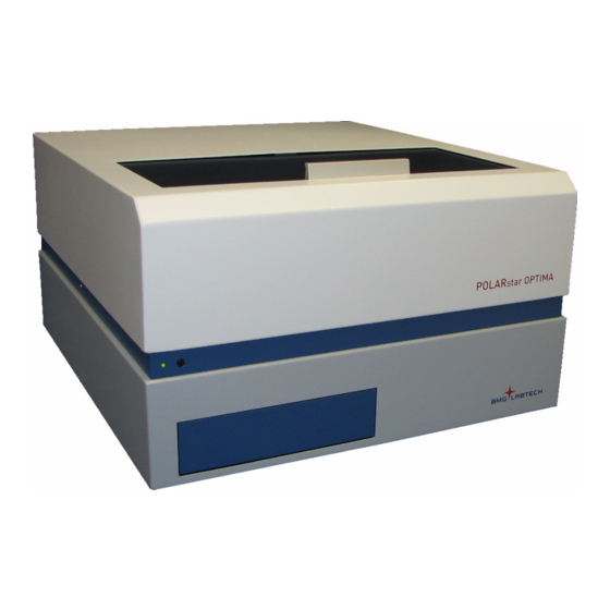
- Page 3 BMG LABTECH FLUOstar / POLARstar / LUMIstar OPTIMA Operating Manual The FLUOstar OPTIMA is a multifunctional microplate reader that can perform a wide variety of applications for fluorescence intensity, time-resolved fluorescence, absorbance and luminescence. The POLARstar OPTIMA can measure in the above-mentioned modes and additionally in fluorescence polarization mode and simultaneous dual emission.
-
Page 4: Table Of Contents
FLUOstar / POLARstar / LUMIstar OPTIMA Operating Manual BMG LABTECH TABLE OF CONTENTS TECHNICAL SPECIFICATIONS INSTALLATION RANSPORT OWER AND OMMUNICATION ONNECTIONS INSTRUMENT OVERVIEW DESCRIPTION OF COMPONENTS PTICS NSTALLATION AND HANGING OF PTICS 4.2.1 OMBINATION PTICS LUORESCENCE NTENSITY AND BSORBANCE 4.2.2... -
Page 5: Technical Specifications
FLUOstar OPTIMA & POLARstar OPTIMA: - High-energy xenon flash-lamp Detector: Side window, current type photomultiplier tube Filters: FLUOstar OPTIMA & POLARstar OPTIMA: - 2 filter wheels: with 8 excitation and 8 emission filter positions LUMIstar OPTIMA: - Emission filter wheel with 8 filter positions Gain control:... - Page 6 Fuses: - T2.5A/250V for main power 230 V - T3.15A/250V for main power 115 V - T3.15A/250V for main power 100 V (use original spare fuses provided by BMG LABTECH only) Dimensions: Height: 27 cm, width: 44 cm and length 48 cm...
-
Page 7: Installation
T3.15A/250V for main power 100 V - injector needle cleaner (if with reagent injectors) Call BMG LABTECH immediately if any of these items are missing. The area designated for the instrument should be free of dust, liquids and acidic vapours. The table's surface should be flat and even. -
Page 8: Power Andc
• Connection Check Locate the RS232 cable (9-pin type) in the shipping box. Connect it to the FLUOstar OPTIMA (or POLARstar OPTIMA or LUMIstar OPTIMA) and to the RS232 port on the PC. Only connect a computer that corresponds to EN 60950 and UL 1950 for data processing instruments In order to make a ‘Connection check’, the software needs to be installed. -
Page 9: Instrument Overview
Offset values (no further notice needed because this number has been entered into the reader at the factory) On /Off Power cable Serial number RS-232 Switch connector connector Figure 7: Back of FLUOstar OPTIMA, POLARstar OPTIMA and LUMIstar OPTIMA 2007-11-19 0413B0001I 9/23... - Page 10 Measurement head position Injection needle holder Bottom optic Figure 8: FLUOstar OPTIMA & POLARstar OPTIMA top view of reagent box with combi-optic and 2 reagent injectors Top View, Reagent Box LUMIstar OPTIMA Filter wheel cover Reagent injectors (optional) (for emission filter wheel)
-
Page 11: Description Of Components
BMG LABTECH FLUOstar / POLARstar / LUMIstar OPTIMA Operating Manual 4 Description of Components 4.1 Optics All standard equipped readers have UV/Vis optics for top reading. For optimal performance, there are different top reading optics available for fluorescence intensity, fluorescence polarization, luminescence, absorbance and time-resolved fluorescence. - Page 12 FLUOstar / POLARstar / LUMIstar OPTIMA Operating Manual BMG LABTECH 4.2.1 Combination Optics (Fluorescence Intensity and Absorbance) The combination optic is made up of two liquid-filled light guides for fluorescence intensity and a quartz fiber for absorbance measurement (figure 12).
- Page 13 BMG LABTECH FLUOstar / POLARstar / LUMIstar OPTIMA Operating Manual 4.2.2 Fluorescence Intensity Optics The fluorescence intensity and time-resolved fluorescence light guides are liquid-filled and should be connected to the excitation and emission positioning wheels. To position the measurement head with the holders, see chapter 4.2 Installation and Changing of Optics.
- Page 14 FLUOstar / POLARstar / LUMIstar OPTIMA Operating Manual BMG LABTECH 4.2.4 Luminescence Optics The luminescence optic has one light guide, which is silver in colour. The light guide connects to the emission side. To position the measurement head with the holders, see section 4.2 Installation and Changing of Optics.
-
Page 15: Dual Emissiono
(PMT 2). Only the POLARstar OPTIMA can measure fluorescence polarization. It is possible to upgrade the FLUOstar OPTIMA to a POLARstar OPTIMA. Regarding filters for fluorescence polarization, see chapter 4.4.3. -
Page 16: Bottom Optics
FLUOstar / POLARstar / LUMIstar OPTIMA Operating Manual BMG LABTECH 4.2.8 Bottom Optics The bottom optics are used to measure fluorescence, luminescence and absorbance. The bottom optics enter the reagent box on the left side and are connected to the left position of the excitation and emission wheels. -
Page 17: Filters
Please be careful when positioning the needle. 4.4 Filters In the FLUOstar Optima, 4 excitation and 4 emission filters are factory installed, in the POLARstar OPTIMA, 4 excitation and 5 emission filters are factory installed. (Filter selection varies with instrument configuration. If your unit is equipped with luminescence, then a lens will be installed. - Page 18 FLUOstar / POLARstar / LUMIstar OPTIMA Operating Manual BMG LABTECH The excitation filters and the emission filters are located in their respective filter wheels behind the filter wheel cover (figure 27 to figure 29). To access the filters, first remove the light guides. The filter wheel cover can then be removed by loosening the 4 thumbscrews (figure 28).
-
Page 19: Dual Emissionf
BMG LABTECH FLUOstar / POLARstar / LUMIstar OPTIMA Operating Manual Next to the axle in the center of the housing is a small positioning pin. This pin must fit into one of the holes on the back of the filter wheel. Replace the filter wheel on the axle and push it in position (the axle should stick out 3mm). -
Page 20: Spacers
FLUOstar / POLARstar / LUMIstar OPTIMA Operating Manual BMG LABTECH 4.5 Spacers The FLUOstar, POLARstar and LUMIstar OPTIMA are designed for most plate formats. The height of some microplates exceeds the space allowed under the optics. The minimum space between the optics and microplate should be 1.5 mm. -
Page 21: Reagent Injectors
BMG LABTECH FLUOstar / POLARstar / LUMIstar OPTIMA Operating Manual 4.6 Reagent Injectors The FLUOstar, POLARstar as well as the LUMIstar OPTIMA can all be equipped with up to 2 reagent injectors (figure 33). Figure 33: Reagent injectors When the reagent injector(s) are not in use, the needle(s) can be placed in the needle holder (figure 8). -
Page 22: Instrument Disinfection
FLUOstar / POLARstar / LUMIstar OPTIMA Operating Manual BMG LABTECH 5 Instrument Disinfection Please follow all instructions carefully for a successful disinfection of the FLUOstar, POLARstar and LUMIstar OPTIMA. All parts of the instrument, which have the possibility of contacting patient sera or positive samples, have to be handled as if they are hazardous. - Page 23 Disinfection Certification This instrument and its inventory have never been in contact with any dangerous biological material, or if so, the instrument and its inventory have been disinfected according to the instructions of the operating manual of instrument. ________________________________________________ Name: Company ________________________________________________ ________________________________________________...
Need help?
Do you have a question about the FLUOstar OPTIMA and is the answer not in the manual?
Questions and answers