
Related Manuals for Distek 2500


Summary of Contents for Distek 2500
- Page 1 Model 2500 Document: 3825-0001 Rev. F © 2015-2017 Distek, Inc. All Rights Reserved Operation Manual...
- Page 2 Model 2500 Operation Manual Document 3825-0001 Rev. F © Distek , Inc. 121 North Center Dr. • North Brunswick , NJ 08902 Phone 732.422.7585 • Fax 732.422.7310 http://www.distek inc.com...
- Page 3 In no event shall Distek, Inc. be liable for any loss of profit or any other commercial damage caused or alleged to have been caused directly or indirectly by this document.
-
Page 4: Table Of Contents
4 Distek Cipher Software ........................... 47 5 Agilent 8453 UV-Vis ........................... 48 6 Waters HPLC ........................... 49 Graphic User Interface (GUI) Chapter IV 1 2500 Dashboard ........................... 52 2 2500 RTD Dashboard ........................... 54 © 2015-2017 Distek, Inc. A ll Rights Reserved... - Page 5 ................................135 Edit User ................................137 Delete User 10 System Settings ........................... 138 ................................139 TCS Sc hedule ................................141 Temperature Calibration ................................. 142 Accessing Calibration ................................. 144 TCS Calibration Using TempChek © 2015-2017 Distek, Inc. A ll Rights Reserved...
- Page 6 ........................... 189 7 Temperature Calibration ........................... 190 8 Mechanical ........................... 191 Chapter VIII Appendix A: Spare Parts and Accessories Chapter IX Appendix B: Pre-Installation Considerations Chapter X Appendix C: Sample Printouts Index © 2015-2017 Distek, Inc. A ll Rights Reserved...
- Page 7 Chapter Introduction...
-
Page 8: Chapter I Introduction
Model 2500 Overview Instrument Specification Notices Safety Information Site Requirements Environmental Conditions This chapter contains an overview of the instrument and safeguards that need to be followed when installing and using the instrument. © 2015-2017 Distek, Inc. A ll Rights Reserved... -
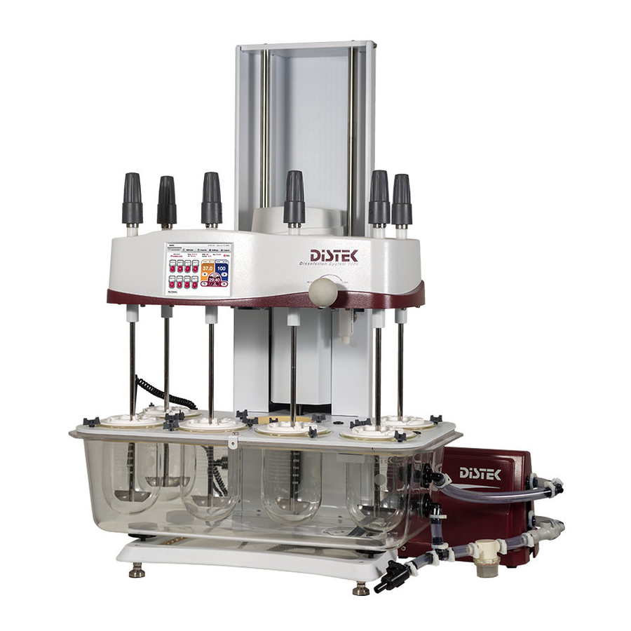
Page 9: Distek Model 2500 Overview
Distek Model 2500 Overview W elcome to a new innova tion in Dissolution testing . The Distek Model 2500 Dissolution Test System offers unmatched flexibility and configurability while maintaining the user-friendliness that laboratories around the world have come to expect from the preceding four generations of the 2100 series. - Page 10 Accommodates up to 8 vessels ranging in size from 100mL to 4L, allowing the user to run a diverse range of tests. W orks w ith Distek line of Dissolution equipment a nd softw a re. The instrument is compatible with the following equipment/software: Eclipse 5300 EVO 4300 with Firmware Revision 3.01 or higher...
-
Page 11: Instrument Specification
Less than 0.010” (0.254mm) Total Indicator Runout o Manual o Automatic (100 maximum saved Pre-Programmed Methods) Program Modes o Distek EVO 4300, Distek OPT-DISS 405 UV, Agilent UV-Vis 8453, Waters 2695D HPLC User Management Manage up to 50 Users with Multiple Access Level... -
Page 12: Notices
Notices © Distek, Inc. 2015-2017 No part of this document may be reproduced in any form or by any means without written consent from Distek Inc., as governed by United States and/or International copyright laws. Manual Part Number 3825-0001 Document Revision History... - Page 13 The Material in this document is provided "as is", and is subject to changes without notice in future revisions. Distek disclaims all warranties, either express or implied, with regard to this manual and any information contained herein, including but not limited to the implied warranties of merchantability and fitness for a particular purpose.
-
Page 14: Safety Information
Failure to comply with these precautions or warnings elsewhere in this manual violates the safety standard of the design, manufacture and intended use of this instrument. Distek Inc. assumes no liability for the customer or end-user to comply with these requirements. -
Page 15: Site Requirements
Model 2500 Introduction Site Requirements Physical Site Consideration Electrical Requirements This chapter contains information regarding the recommended minimum available bench space, electrical requirements and environmental conditions when installing your instrument. © 2015-2017 Distek, Inc. A ll Rights Reserved... -
Page 16: Physical Site Consideration
Introduction 1.5.1 Physical Site Consideration The dimensional requirements specified below are adequate for the installation of the Model 2500 Dissolution System: The minimum bench depth needed (front edge of bench to the back splash or wall) is 22 inches (56cm). However, the minimum recommended bench depth is 25 inches (64cm) for proper ventilation. -
Page 17: Electrical Requirements
Always use the power cord supplied with your instrument. Always plug in your instrument with a properly grounded wall outlet. © 2015-2017 Distek, Inc. A ll Rights Reserved... -
Page 18: Environmental Conditions
This chapter contains information regarding the recommended laboratory conditions such as humidity, room temperature and air quality when installing your instrument. It also contains information regarding environmental considerations when disposing of the instrument. © 2015-2017 Distek, Inc. A ll Rights Reserved... -
Page 19: Ambient Laboratory Humidity
Maximum: The Model 2500 Series may add to the humidity of the laboratory during operation. Any vessels filled and left uncovered can raise humidity levels. Water vapor and/or hydrogen chloride vapor from dissolution media can cause serious effects when condensed on electrical components and contacts. -
Page 20: Ambient Laboratory Temperature
To achieve the full range of controlled operation (20 to 65°C) within specified tolerances, the Model 2500 Series Dissolution System is designed to be installed and operated in laboratories where the maximum operating temperature does not exceed 25°C. The maximum allowable ambient operation temperature is 30°C. -
Page 21: Air Quality Considerations
1.6.3 Air Quality Considerations Distek dissolution systems are designed to be operated in a laboratory environment that has no visible dust problem and with organic solvent vapor levels as low as possible. Operation is not recommended in dusty lab environments, or in labs with significant chlorinated or reactive solvent vapor levels. -
Page 22: Environmental Considerations
Environmental Considerations Distek & the WEEE Directive (Waste Electrical & Electronic Equipment) Distek, Inc. is committed to protecting the environment and understands the importance of proper recycling. The “crossed out wheelie bin” symbol on the product or on its packaging indicates that this product must not be disposed of with domestic household waste. - Page 23 Chapter Installation...
-
Page 24: Chapter Ii Installation
This chapter contains an overview of the instrument and how to properly level the instrument. It also contains information on how to properly install the vessels, paddles, baskets and adaptors and vessel covers. © 2015-2017 Distek, Inc. A ll Rights Reserved... -
Page 25: Unpacking
Please take a few moments when unpacking the Distek Model 2500 Dissolution instrument to check for all items indicated on the packing list. Notify Distek or your shipper immediately of any discrepancies or damage to cartons or contents in transit. -
Page 26: Leveling
OPTIONAL: Mark the location of the leveling feet on the bench to prevent changes in level due to moving the unit. Check the level after completing installation, or after moving the instrument to a new location. Verify the level from front to back and side to side. © 2015-2017 Distek, Inc. A ll Rights Reserved... -
Page 27: Ac Power Installation
With the instrument positioned properly on the bench and leveled, locate the AC power inlet and outlet on the lower left hand side of the instrument. Connect the power cord extension labeled AC Out TCS - for 2500 and 2500 RTD. Connect the supplied main power cord labeled AC In . -
Page 28: Tcs Installation
Model 2500 Installation TCS Installation To install the TCS for 2500 and 2500RTD, follow the procedure below: Position the thermo-circulator behind the right side of the bath with the TCS fittings facing the right side. Connect the power cord extension to the power port of the TCS and the other end to the main unit. - Page 29 Clean the inside of the bath for any packaging material that might lodge inside and damage the pump during normal operation. The pump is self priming so there is no need to prime the TCS. Do not let the pump run dry. © 2015-2017 Distek, Inc. A ll Rights Reserved...
-
Page 30: Vessel Installation
To install vessels, follow the procedure below: Raise the drive unit. For 2500 and 2500 RTD: Locate the white arrow on the vessel flange then insert a vessel in each position and use the vessel clips on the vessel plate to hold them in place. - Page 31 Model 2500 Installation Distek supplies highly uniform vessels that fit properly into the Model 2500. Use of vessels other than those supplied by Distek may result in unsatisfactory operation and potentially void the warranty or may cause faulty results. © 2015-2017 Distek, Inc. A ll Rights Reserved...
-
Page 32: Shaft Installation
Standard Shafts Wireless Sensor Shafts The Model 2500 as a standard comes with standard solid shafts. As an option, RTD wireless sensor shafts were added to monitor individual vessel temperature. If shafts are serialized, follow the Production Final Test report for spindle location. -
Page 33: Standard Shafts
From the bottom of the spindle, insert a shaft in each spindle position. Shaft installation Install the shaft collars on the top end of each shaft and leave them loose. Shaft collar © 2015-2017 Distek, Inc. A ll Rights Reserved... -
Page 34: Rtd Shafts
Removing shaft adapter cover Carefully insert the battery into the battery holder and route the battery wires inside the wire channel as shown. © 2015-2017 Distek, Inc. A ll Rights Reserved... - Page 35 Reinstall the shaft cover. Make sure that the cover is engaged and locked in place with the release buttons. If the shafts needs to be removed for cleaning, it is important that the shafts remained in their original location to maintain temperature accuracy response. © 2015-2017 Distek, Inc. A ll Rights Reserved...
-
Page 36: Paddle Installation
Distek supplies highly uniform paddle blades that fit properly into the Model 2500 shafts. Use of paddle blades other than those supplied by Distek for the Model 2500 may result in unsatisfactory height adjustment. © 2015-2017 Distek, Inc. A ll Rights Reserved... -
Page 37: Basket Installation
Distek supplies highly uniform baskets that fit properly into the Model 2500 shafts. Use of baskets other than those supplied by Distek for the Model 2500 may result in unsatisfactory height adjustment. © 2015-2017 Distek, Inc. A ll Rights Reserved... -
Page 38: Vessel Covers
Installation Vessel Covers There are multiple cover designs you can use with the Model 2500 to minimize evaporation. All Distek vessel covers place the sampling probes at the precise sampling height as per USP, BP, EP and JP standards, the midpoint between the top of the stirring element and the top of the media. -
Page 39: Chapter Iii Installing Accessories
Chapter Installing Accessories... -
Page 40: Installing Accessories
This chapter briefly describes the available accessories and outlines how to install the accessories. The accessories are available to enhance the functionality and capabilities of your dissolution bath. Detailed information about these accessories is included in separate manuals. © 2015-2017 Distek, Inc. A ll Rights Reserved... -
Page 41: Tempchek
The TempChek is an ultra-high accuracy resolution, hand-held digital thermometer that uses a YSI series precision thermistor. Along with an RS-232 port, it allows temperature data from the TempChek to be sent to the Model 2500 to calibrate the TCS temperature sensors and or the RTD wireless shafts. -
Page 42: Dosage Delivery System (Dds)
Attach the Dosage Delivery System modules on each vessel cover. Notice that the vessel cover has two slotted holes to allow the DDS module pegs to fit securely. Dosage Delivery System installation © 2015-2017 Distek, Inc. A ll Rights Reserved... - Page 43 The connectors are keyed and as a guide, there's a white arrow indicator on each connector. Keyed connector plug and receptacle A properly installed Dosage Delivery System should resemble the photo below. Dosage Deliver System installed © 2015-2017 Distek, Inc. A ll Rights Reserved...
- Page 44 DDS from the DDS rail and store in the drawer. The use of connector rubber caps may also be used to prevent possible corrosion on the electrical contacts. Placement for DDS when not in use © 2015-2017 Distek, Inc. A ll Rights Reserved...
-
Page 45: Printers
The default instrument printer setup is set to USB. Model 2500 local printer connection The Model 2500 can also be connected through a network printer by following the setup below: Log into the instrument as part of the Manager group. The select Setting s | System Setting s | System Setup . -
Page 46: Dedicated Instrument Printer
3.3.1 Dedicated Instrument Printer Another option to connect Distek instruments (Models 2500, symphony 7100, sensIR 3200 and Eclipse 5300) is to have a dedicated instrument printer instead of having a local printers for each instruments or connecting the instruments to print through the domain. -
Page 47: Distek Cipher Software
Cipher instrument control software is a Windows based application designed and developed by Distek to remotely access and control the dissolution equipment. Cipher can be installed locally or networked to provide full access to any Distek dissolution bath and autosampler from any appropriately connected PC running the application. Cipher allows the user to create and run methods, monitor instrument status, generate reports, and control users and manager logins. -
Page 48: Agilent 8453 Uv-Vis
RS-232 port (COM port) to configure either single or multiple baths connected to the PC serial ports. This has been made possible due to the capability of the RS-232 port in Distek Model 2500 Dissolution Systems (a NULL RS-232 cable is required). -
Page 49: Waters Hplc
Local or remote control with Empower Dissolution Software Custom dissolution calculations Publication-quality report publisher Model 2500 with Waters 2695D A NULL RS-232 cable is required to connect the Model 2500 with Waters HPLC. © 2015-2017 Distek, Inc. A ll Rights Reserved... -
Page 50: Chapter Iv Graphic User Interface (Gui)
Chapter Graphic User Interface (GUI) -
Page 51: Graphic User Interface (Gui)
Settings tab. Logout: This screen is used to log the user out from the instrument GUI. © 2015-2017 Distek, Inc. A ll Rights Reserved... -
Page 52: 2500 Dashboard
Model 2500 Graphic User Interface (GUI) 2500 Dashboard This is the main display screen of the Model 2500 instrument. It gives you access to available menus. Below is a brief description of the function of each item. 2500 Dashboard Screen Title Bar: Shows the Distek logo, current time and date. - Page 53 Model 2500 Graphic User Interface (GUI) Sampling Time Display: Displays the sampling time when a method test is started. Method Parameter Table: Displays the summary of the method when running a test. © 2015-2017 Distek, Inc. A ll Rights Reserved...
-
Page 54: 2500 Rtd Dashboard
Below is a brief description of the function of each item. 2500 RTD Dashboard Screen Title Bar: Shows the Distek logo, current time and date. Menu Tabs: Used to navigate throughout the software. User Login Name: Displays who is logged in to the instrument. - Page 55 Sampling Time Display: Displays the sampling time when a method test is started. Active DDS: If equipped, displays that the dosage delivery system is enabled. Can also be used to manually enable the DDS. © 2015-2017 Distek, Inc. A ll Rights Reserved...
-
Page 56: 2500 Select Dashboard
Below is a brief description of the function of each item. 2500 RTD Dashboard Screen Title Bar: Shows the Distek logo, current time and date. Menu Tabs: Used to navigate throughout the software. Method Name (or Manual): Shows the selected Method when running; otherwise, shows a manual run. - Page 57 Graphic User Interface (GUI) Sampling Time Display: Displays the sampling time when a method test is started. Apparatus and Volume Control: Allows operator to set the desired apparatus to use and volume in vessel. © 2015-2017 Distek, Inc. A ll Rights Reserved...
-
Page 58: Apparatus Id
Every time the Apparatus ID screen is accessed, the instrument will verify that each shaft were not moved or replaced. If there are changes, the application will alert the operator that changes were made. Apparatus ID Screen © 2015-2017 Distek, Inc. A ll Rights Reserved... -
Page 59: Methods
Delete: After selecting the desired method, user who has a manager privilege can delete the method. Print: After selecting the desired method, user can print the method. USB: The end-user is able to Import or Export using a USB flash drive. © 2015-2017 Distek, Inc. A ll Rights Reserved... -
Page 60: Reports
A library of up to 100 reports is stored in the instrument. Once the number of reports reaches the maximum amount, the oldest report will be over-written. The exported reports are converted automatically to CSV files. © 2015-2017 Distek, Inc. A ll Rights Reserved... -
Page 61: Settings
System Settings: Perform instrument system setup, shaft calibration, service upgrades and instrument validation. Help: Information regarding on how to use the instrument and how to contact Distek if you encounter any issues with the instrument. Help also contains the instrument serial numbers, identification and firmware revisions. -
Page 62: Logout
When the instrument is idle and the end-user wants to exit the software, select the Log out tab to log out from the software application. 2500 Logout tab. User cannot log out if there is a test running. Ability to log out is available on all screens. © 2015-2017 Distek, Inc. A ll Rights Reserved... -
Page 63: On-Screen Keyboard
Enter key will accept the changes ESC key will close the On-Screen Keyboard UP Arrow key is the Shift key (Upper/Lower case letters and symbols) Double-click UP Arrow key is the Caps Lock © 2015-2017 Distek, Inc. A ll Rights Reserved... -
Page 64: Chapter V Operation
Chapter Operation... -
Page 65: Chapter V Operation
This chapter describes the operation of the instrument, including turning on the instrument, operational checkout, apparatus height adjustments, how to create a new method, edit an existing method, how to run manually and user setup and system settings. © 2015-2017 Distek, Inc. A ll Rights Reserved... -
Page 66: Turning On The Instrument
Select your log in name and an on-screen keypad will be displayed for the user to type in their password. Login Screen Pressing ESC on the keypad closes the on-screen keypad. © 2015-2017 Distek, Inc. A ll Rights Reserved... -
Page 67: Operational Checkout
Instrument meets the validation criteria and does not display the expired calibration date, if activated. Correct apparatus is attached to the shafts. Proper height of the apparatus that will be used after engaging the height adjustment setting to the proper position. © 2015-2017 Distek, Inc. A ll Rights Reserved... -
Page 68: Height Adjustment
Modified Paddles Intrinsic The apparatus height is set and configured for baskets and paddles purchased at Distek, and should not have to be changed unless the height is out of specification. For better height adjustment reproducibility, it is recommended to keep vessels in the same position after emptying and washing. -
Page 69: Baskets And Paddles
"Lock" indicator, to lock the drive head in place. Position the height setting to N eutra l by positioning the Quick Height Adjustment block to horizontal position. See figure below for reference. © 2015-2017 Distek, Inc. A ll Rights Reserved... - Page 70 For better height adjustment reproducibility, it is recommended to keep vessels in the same position after emptying and washing. © 2015-2017 Distek, Inc. A ll Rights Reserved...
- Page 71 Lower the drive head and turn the knob to lock position. The distance of 25±2 mm between the blade and the inside bottom of the vessel is set and maintained during the test. © 2015-2017 Distek, Inc. A ll Rights Reserved...
- Page 72 When using baskets, simply switch the paddle blades for basket adapters and move the height adjustment setting to Baskets. See Basket Installation. © 2015-2017 Distek, Inc. A ll Rights Reserved...
-
Page 73: Modified Baskets
Gently slide each shaft halfway up through each spindle. If shafts are hard to to slide, a very thin film of vacuum grease applied on the top end of the shaft will allow it to slide smoothly. © 2015-2017 Distek, Inc. A ll Rights Reserved... - Page 74 Fully raise the drive head and turn the knob to lock position. Discard the masking tape. Lower the drive head and turn the knob to lock position. The distance between the rotating cylinder and the inside bottom of the vessel is set and maintained during the test. © 2015-2017 Distek, Inc. A ll Rights Reserved...
-
Page 75: Modified Paddles
"Lock" indicator, to lock the drive head in place. Position the height setting to N eutra l by positioning the Quick Height Adjustment block to horizontal position. See figure below for reference. Height adjustment block in horizontal position © 2015-2017 Distek, Inc. A ll Rights Reserved... - Page 76 Height adjustment block position for modified paddles Lower the drive head and turn the knob to lock position. The bottom of the paddle blade and the top-side of the disk assembly is set and maintained during the test. © 2015-2017 Distek, Inc. A ll Rights Reserved...
-
Page 77: Intrinsic
Loosen the locking collar on each shaft. Position each intrinsic disc inside the vessel. Lower the drive head onto the height adjustment block and turn the drive lift knob to lock position. © 2015-2017 Distek, Inc. A ll Rights Reserved... - Page 78 Height adjustment block position for intrinsic Lower the drive head and turn the knob to lock position. The distance between the intrinsic disc and the paddle is set and maintained during the test. © 2015-2017 Distek, Inc. A ll Rights Reserved...
-
Page 79: Manual Run
Manual Run 5.4.1 2500 with Standard Shafts This section describes how to use the Model 2500 instrument in Manual Run. From the Dashboard, set the temperature by selecting temperature display. Enter the desired temperature using the on-screen keypad. Start heating by selecting the Pla y button. - Page 80 "Active DDS" (Firmware Rev. 1.04 and older labeled "Activate Tablet Dropper") after the stirring has started and the set temperature in vessels has been reached, as shown. Manually activating the Dosage Delivery System © 2015-2017 Distek, Inc. A ll Rights Reserved...
-
Page 81: 2500 Rtd
Operation 5.4.2 2500 RTD This section describes how to use the Model 2500 with Wireless Sensors in Manual Run. From the Dashboard, set the temperature by selecting temperature display. Enter the desired temperature using the on-screen keypad. Start heating by selecting the Pla y button. - Page 82 For manual operation of the Dosage Delivery System, the end-user can activate the tablet dropper by simply selecting the "Active DDS" after the stirring has started and the set temperature has been reached, as shown. Manually activating the Dosage Delivery System © 2015-2017 Distek, Inc. A ll Rights Reserved...
-
Page 83: 2500 Select
5.4.3 2500 Select This section describes how to use the Model 2500 with Wireless Sensors in Manual Run. Every time a method is started, the instrument will verify that each shaft were not moved or replaced. If there are changes, the application will alert the operator that changes were made. - Page 84 For manual operation of the Dosage Delivery System, the end-user can activate the tablet dropper by simply selecting the "Active DDS" after the stirring has started and the set temperature has been reached, as shown. Manually activating the Dosage Delivery System © 2015-2017 Distek, Inc. A ll Rights Reserved...
-
Page 85: Create A New Method
Select the parameter(s) you want to change in the method. Once all bath parameters meet criteria, Sa ve the method. © 2015-2017 Distek, Inc. A ll Rights Reserved... - Page 86 Ba sket, M odified Pa ddles, Intrinsic. Temperature range is from 20.0°C to 65.0°C . Volume range is from 500mL to 1000mL. Enable which vessels will be used (available only to 2500 RTD and Select). RPM range is from 30 to 300 RPM.
- Page 87 Set the time when to change or add the media during test. Cancel: Closes the Create New Method screen. Save: Saves the method. Print: Prints the method, provided a printer is configured. Delete Sampling Points: Deletes selected sampling point. © 2015-2017 Distek, Inc. A ll Rights Reserved...
-
Page 88: Edit Method
In the Edit Method screen, select and edit the parameter(s) you want to change in the method. Once all changes are made, Sa ve the method. © 2015-2017 Distek, Inc. A ll Rights Reserved... - Page 89 2500RTD Edit Method Screen There will be a maximum of 50 changes on an existing method that will be reported as part of the audit trail. These can be viewed when the method is printed. © 2015-2017 Distek, Inc. A ll Rights Reserved...
-
Page 90: Method Run
Every time a method is started, the instrument will verify that each shaft were not moved or replaced. If there are changes, the application will alert the operator that changes were made. © 2015-2017 Distek, Inc. A ll Rights Reserved... -
Page 91: Selecting A Method
View: When logged in as part of the User group, operator can only view the method. Run: Start to run selected method. Delete: Erase selected method. Print: Print a method report, if printer is configured. USB: Importing or exporting the methods using a USB thumb drive. © 2015-2017 Distek, Inc. A ll Rights Reserved... -
Page 92: Using The Dosage Delivery System
Specifying time for DDS Once the 'Warming Up' is complete, depending on the criteria and method chosen, the samples are introduced simultaneously or staggered and the test timer starts. © 2015-2017 Distek, Inc. A ll Rights Reserved... -
Page 93: Simultaneous Drop Using Baskets
Simultaneous Drop Using Baskets 5.7.3.1 2500 with Standard Shafts This section describes how to run the Model 2500 using baskets for simultaneous sampling. Choose M ethods tab. The Select Method screen displays the method listing. Select the desired method you want to run. - Page 94 After the instrument has completed a warming up period, a status window prompts the operator to verify the temperature of the media inside the vessels. Once vessel temperatures are verified, select Yes to continue. Verify, raise drive and introduce dosage © 2015-2017 Distek, Inc. A ll Rights Reserved...
- Page 95 Collect all samples at zero seconds, as shown in sampling time display at zero seconds. This step will repeat if the method is programmed to have multiple sampling intervals. © 2015-2017 Distek, Inc. A ll Rights Reserved...
- Page 96 After the last sampling time, the instrument will run for an extra minute, then a dialog message screen appears after completing the test. Select OK to close the prompt display screen. Test completed © 2015-2017 Distek, Inc. A ll Rights Reserved...
-
Page 97: 2500 Rtd-Select
Operation 5.7.3.2 2500 RTD-Select This section describes how to run the Model 2500 with Wireless Sensors using baskets for simultaneous sampling. Choose M ethods tab. The Select Method screen displays the method listing. Select the desired method you want to run. - Page 98 After the instrument has completed a warming up period, a status window prompts the operator to verify the temperature of the media inside the vessels. Once vessel temperatures are verified, select Sta rt to continue. Verifying vessel temperature © 2015-2017 Distek, Inc. A ll Rights Reserved...
- Page 99 Collect all samples at zero seconds. This step will repeat if the method is programmed to have multiple sampling intervals. © 2015-2017 Distek, Inc. A ll Rights Reserved...
- Page 100 After the last sampling time, the instrument will run for an extra minute, then a dialog message screen appears after completing the test. Select OK to close the prompt display screen. Test completed © 2015-2017 Distek, Inc. A ll Rights Reserved...
-
Page 101: Simultaneous Drop Using Paddles
Simultaneous Drop Using Paddles 5.7.4.1 2500 with Standard Shafts This section describes how to run the Model 2500 using paddles for simultaneous sampling. Choose M ethods tab. The Select Method screen displays the method listing. Select the desired method you want to run. - Page 102 After the instrument has completed a warming up period, a dialog window prompts the operator to verify the temperature of the media inside the vessels. Once vessel temperatures are verified, select Yes to pause the stirring. Verify temperature and pause stirring © 2015-2017 Distek, Inc. A ll Rights Reserved...
- Page 103 Collect all samples at zero seconds, as shown in sampling time display at zero seconds. This step will repeat if the method is programmed to have multiple sampling intervals. © 2015-2017 Distek, Inc. A ll Rights Reserved...
- Page 104 After the last sampling time, the instrument will run for an extra minute, then a dialog message screen appears after completing the test. Select OK to close the prompt display screen. Test completed © 2015-2017 Distek, Inc. A ll Rights Reserved...
-
Page 105: 2500 Rtd-Select
Operation 5.7.4.2 2500 RTD-Select This section describes how to run the Model 2500 with Wireless Sensors using paddles for simultaneous sampling. Choose M ethods tab. The Select Method screen displays the method listing. Select the desired method you want to run. - Page 106 After the instrument has completed a warming up period, a dialog window prompts the operator to verify the temperature of the media inside the vessels. Once vessel temperatures are verified, select Yes to continue. Verifying vessel temperature © 2015-2017 Distek, Inc. A ll Rights Reserved...
- Page 107 Collect all samples at zero seconds. This step will repeat if the method is programmed to have multiple sampling intervals. © 2015-2017 Distek, Inc. A ll Rights Reserved...
- Page 108 After the last sampling time, the instrument will run for an extra minute, then a dialog message screen appears after completing the test. Select OK to close the prompt display screen. Test completed © 2015-2017 Distek, Inc. A ll Rights Reserved...
-
Page 109: Staggered Drop Using Baskets
Staggered Drop Using Baskets 5.7.5.1 2500 with Standard Shafts This section describes how to run staggered sampling with the Model 2500 using baskets. Choose M ethods tab. The Select Method screen displays the method listing. Select the desired method you want to run. - Page 110 Method Started After the instrument has completed a warming up period, click OK at status window after user verifies the temperature of the media inside the vessels. User verifies the vessel temperature © 2015-2017 Distek, Inc. A ll Rights Reserved...
- Page 111 When position 2 staggered time is reached, another dialog window prompts the user to attach basket 2 then lower shaft 2 either when the timer reached 0 or by pressing Start. This step will be repeated for the remaining enabled vessels. © 2015-2017 Distek, Inc. A ll Rights Reserved...
- Page 112 Sampling time reached for position 1 After the last sampling time, the instrument will run for an extra minute, then a dialog message screen appears after completing the test. Select OK to close the prompt display screen. © 2015-2017 Distek, Inc. A ll Rights Reserved...
- Page 113 Model 2500 Operation Test completed © 2015-2017 Distek, Inc. A ll Rights Reserved...
-
Page 114: 2500 Rtd-Select
Operation 5.7.5.2 2500 RTD-Select This section describes how to run staggered sampling with the Model 2500 with Wireless Sensors using baskets. Choose M ethods tab. The Select Method screen displays the method listing. Select the desired method you want to run. - Page 115 Method Started After the instrument has completed a warming up period, click OK at status window after user verifies the temperature of the media inside the vessels. User verifies the vessel temperature © 2015-2017 Distek, Inc. A ll Rights Reserved...
- Page 116 When position 2 staggered time is reached, another dialog window prompts the user to attach basket 2 then lower shaft 2 either when the timer reached 0 or by pressing Start to continue. This step will be repeated for the remaining enabled vessels. © 2015-2017 Distek, Inc. A ll Rights Reserved...
- Page 117 Sampling time reached for position 1 After the last sampling time, the instrument will run for an extra minute, then a dialog message screen appears after completing the test. Select OK to close the prompt display screen. © 2015-2017 Distek, Inc. A ll Rights Reserved...
- Page 118 Model 2500 Operation Test completed © 2015-2017 Distek, Inc. A ll Rights Reserved...
-
Page 119: Staggered Drop Using Paddles
Staggered Drop Using Paddles 5.7.6.1 2500 with Standard Shafts This section describes how to run the Model 2500 using paddles using staggered sampling. Choose M ethods tab. The Select Method screen displays the method listing. Select the desired method you want to run. - Page 120 Method started After the instrument has completed a warming up period, click OK at status window after user verifies the temperature of the media inside the vessels. User verifies the vessel temperature © 2015-2017 Distek, Inc. A ll Rights Reserved...
- Page 121 2 to stop stirring. Then the user is prompted to introduce the dosage in position 2 when the timer reaches zero. The user can also introduce the dosage by pressing Start to continue. This step will be repeated for the remaining enabled vessels. © 2015-2017 Distek, Inc. A ll Rights Reserved...
- Page 122 Sampling time reached After the last sampling time, the instrument will run for an extra minute, then a dialog message screen appears after completing the test. Select OK to close the prompt display screen. © 2015-2017 Distek, Inc. A ll Rights Reserved...
- Page 123 Model 2500 Operation Test completed © 2015-2017 Distek, Inc. A ll Rights Reserved...
-
Page 124: 2500 Rtd-Select
Operation 5.7.6.2 2500 RTD-Select This section describes how to run staggered sampling with the Model 2500 with Wireless Sensors using baskets. Choose M ethods tab. The Select Method screen displays the method listing. Select the desired method you want to run. - Page 125 Method Started After the instrument has completed a warming up period, click Yes at status window after user verifies the temperature of the media inside the vessels. User verifies the vessel temperature © 2015-2017 Distek, Inc. A ll Rights Reserved...
- Page 126 2 to introduce the second sample into vessel 2. Once the dosage is introduced and settled at the bottom of the vessel, select Introduce Dosa g e to start the test. This step will be repeated for the remaining enabled vessels. © 2015-2017 Distek, Inc. A ll Rights Reserved...
- Page 127 Sampling time reached for position 1 After the last sampling time, the instrument will run for an extra minute, then a dialog message screen appears after completing the test. Select OK to close the prompt display screen. © 2015-2017 Distek, Inc. A ll Rights Reserved...
- Page 128 Model 2500 Operation Test completed © 2015-2017 Distek, Inc. A ll Rights Reserved...
-
Page 129: Report Summary
The report summary displays some of the important test details from the test. The user has the option to print a comprehensive report by selecting the Print button. Model 2500 standard report summary © 2015-2017 Distek, Inc. A ll Rights Reserved... - Page 130 Model 2500 Operation Model 2500 with Wireless sensors test report summary © 2015-2017 Distek, Inc. A ll Rights Reserved...
-
Page 131: User Setup
A user who is part of the Manager group defines the password setting for the individual user when assigning a new account. Then the user can login and change his or her desired password in the User Setup menu. © 2015-2017 Distek, Inc. A ll Rights Reserved... -
Page 132: New User
Select N ew to create a new user. A popup window message prompts user to enter a user name. Select OK and enter the user name using the on-screen keypad. New Users screen © 2015-2017 Distek, Inc. A ll Rights Reserved... - Page 133 (Selecting Ca ncel button nullifies all changes made and returns the user to the User Setup screen.) User Editor screen Confirm that the newly created user is shown in the user list table. User list table © 2015-2017 Distek, Inc. A ll Rights Reserved...
- Page 134 Cancel: Cancels the changes made and exits the User Editor screen. Delete: Deletes the selected user permanently. Edit: Edits the password or access level of a selected user. Print: Prints the user list, provided a printer is connected. © 2015-2017 Distek, Inc. A ll Rights Reserved...
-
Page 135: Edit User
Choose Setting s tab. Then choose U ser Setup on the General Settings screen. User Setup Select the username you want to modify. Click on Edit to display the User Editor. Edit User list screen © 2015-2017 Distek, Inc. A ll Rights Reserved... - Page 136 User Editor screen Selecting the Cancel button nullifies all changes made and returns the user to the User Setup screen. Confirm that the newly edited user is set up with the correct permissions. © 2015-2017 Distek, Inc. A ll Rights Reserved...
-
Page 137: Delete User
Click on Delete to remove the user permanently. An information window message will confirm that the selected user will be deleted. Edit User list screen Confirm that the deleted user cannot be seen on the user list. © 2015-2017 Distek, Inc. A ll Rights Reserved... -
Page 138: 5.10 System Settings
Only users that have Manager group login access can perform and modify the System Settings. Advanced Users and Users are restricted to system settings and can only view some of the instrument settings. © 2015-2017 Distek, Inc. A ll Rights Reserved... -
Page 139: 5.10.1 Tcs Schedule
TCS Schedule is a way to turn on or turn off the circulator heat and motor pump at a given scheduled time to save electricity when the instrument is not in use. The sample screen shots below are ONLY for Model 2500 and 2500RTD. The Model 2500 Select does not have TCS. - Page 140 The function of each command button is shown below: Save: Accept the changes after editing the desired parameter. Pump Off: Turns off the TCS pump. Back: Takes the user out of the current screen. © 2015-2017 Distek, Inc. A ll Rights Reserved...
-
Page 141: 5.10.2 Temperature Calibration
Accurate calibration of the bath temperature sensor is essential for proper operation of the Model 2500 instrument. Factory calibration provides accuracy within ±0.1 °C. Care must be taken when re-calibrating the instrument, in order to realize the full accuracy and proper sensing temperature range. -
Page 142: Accessing Calibration
Selecting the System Settings For Model 2500, select TCS Ca libra tion or Tem pera ture Ca libra tion for wireless sensors. A popup window message prompts user to enter a password to access the temperature calibration mode. Select OK and enter the appropriate password using the on-screen keypad. - Page 143 The TCS Ca libra tion screen is displayed as shown. TCS Calibration Depending on the unit and type of calibration, follow the procedure for either calibration using a TempChek or Reference on the next chapters. © 2015-2017 Distek, Inc. A ll Rights Reserved...
-
Page 144: Tcs Calibration Using Tempchek
If equipped with wireless sensors, perform Lo-Cal first of shafts with bath temperature between 20-23°C. The sample screenshots below are similar for Model 2500 with or without the wireless sensor option. Place the TempChek probe as close as possible next to the external probe inside the bath. - Page 145 TCS external sensor. After calibration of TCS sensors is complete, select Done to exit the calibration screen; otherwise, if equipped with wireless sensors, select Sha ft Ca libra tion to continue. TCS Calibration © 2015-2017 Distek, Inc. A ll Rights Reserved...
-
Page 146: Tcs Calibration Using Reference
If equipped with wireless sensors, perform Lo-Cal of shafts first with bath temperature between 20-23°C. The sample screen shots below are similar for Model 2500 with or without the wireless sensor option. Place the TempChek probe as close as possible next to the external probe inside the bath. -
Page 147: Shaft Sensor Calibration Using Tempchek
Fill the vessels with at least 900mL DI water with temperature between 20°C to 23°C. Follow the steps below to calibrate the RTD shafts using the Distek TempChek. From the TCS Calibration screen, select Sha ft Ca libra tion as shown. - Page 148 Once satisfied with the result, continue the calibration by selecting vessel position 2 and repeat steps 3 to 5. Repeat the above steps for the remaining vessel positions. © 2015-2017 Distek, Inc. A ll Rights Reserved...
- Page 149 Hi-Ca l parameter is updated. Repeat steps 4 to 11 if it does not meet the criteria. Repeat the above steps for the remaining vessel positions. Once the Hi-Cal is complete, exit the shaft calibration screen by selecting Done . © 2015-2017 Distek, Inc. A ll Rights Reserved...
-
Page 150: Shaft Sensor Calibration Using Reference
The Select Vessel to Ca libra te screen is displayed with vessel position 1 automatically selected as shown. Select Vessel to Calibrate screen Place the TempChek probe into vessel 1 and wait for temperature reading to equilibrate. © 2015-2017 Distek, Inc. A ll Rights Reserved... - Page 151 Hi-Ca l parameter is updated. Repeat steps 4 to 11 if it does not meet the criteria. Repeat the above steps for the remaining vessel positions. Once the Hi-Cal is complete, exit the shaft calibration screen by selecting Done . © 2015-2017 Distek, Inc. A ll Rights Reserved...
-
Page 152: 5.10.3 System Setup
Below describes the steps on how to access and modify the System Setup. Choose Setting s tab. Select System Setting s . The System Settings screen will be displayed. Selecting the System Settings © 2015-2017 Distek, Inc. A ll Rights Reserved... - Page 153 In the System Setup screen, you will find a list of settings that can be modified to meet the desired setting or configuration of the instrument. Select the parameter that needs to be modified to meet the desired criteria. © 2015-2017 Distek, Inc. A ll Rights Reserved...
- Page 154 Tablet Dropper: Enable or disable the tablet dropper using On or Off. PreHeat Stir: Enable or disable the preheat stirring using On or Off. Back Light: Enable or disable the bath lighting using On or Off. Save: Saves the settings. © 2015-2017 Distek, Inc. A ll Rights Reserved...
- Page 155 Operation Advanced: Brings the user to the Advanced Setup Screen (requires Manager level and Password). LCD Calibration: Calibrates the sensitivity of the touch screen display. Back: Returns you to the Settings screen. © 2015-2017 Distek, Inc. A ll Rights Reserved...
-
Page 156: Advanced Setup
The steps below describe how to access and modify the Advanced Setup. Choose Setting s tab. Select System Setting s . The System Settings screen will be displayed. Selecting the System Settings Select System Setup . Selecting the System Setup © 2015-2017 Distek, Inc. A ll Rights Reserved... - Page 157 In the A dva nced Setup screen, you will find a list of settings that can be modified to meet the desired setting or configuration of the instrument. Select the parameter that needs to be modified to meet the desired criteria. Sa ve the changes once all parameters meet criteria. © 2015-2017 Distek, Inc. A ll Rights Reserved...
- Page 158 Save: Saves the settings. Back: Returns you to the Settings screen. When External Control is set to Waters interface, a vial icon indicator appears in the left upper corner next to Distek logo. © 2015-2017 Distek, Inc. A ll Rights Reserved...
-
Page 159: Lcd Calibration
The steps below describe how to access and modify the Advanced Setup. Choose Setting s tab. Select System Setting s . The System Settings screen will be displayed. Selecting the System Settings Select System Setup . Selecting the System Setup © 2015-2017 Distek, Inc. A ll Rights Reserved... - Page 160 The LCD calibration screen will be displayed. Using a stylus, follow the instructions on the screen. Once all four coordinates are touched in sequence, the calibration is saved automatically and the screen reverts to System Setup. LCD calibration screen © 2015-2017 Distek, Inc. A ll Rights Reserved...
-
Page 161: 5.10.4 Service
Choose Setting s tab. Select System Setting s . The System Settings screen will be displayed. Selecting the System Settings Select Service . The Service screen will be displayed. Selecting the Service Screen © 2015-2017 Distek, Inc. A ll Rights Reserved... - Page 162 2. Select the type of service you want to perform. The process will take place automatically, and depending on the upgrade, may take several minutes to complete. 3. Once the service is done, reboot the instrument for the new changes to take effect. © 2015-2017 Distek, Inc. A ll Rights Reserved...
- Page 163 Upgrade Application: Application that runs the user interface. Upgrade Platform: Operating system of the instrument. Enable Advanced Shaft Board: Switches the mode of shaft board for bathless instrument only. Back: Returns you to the Settings screen. © 2015-2017 Distek, Inc. A ll Rights Reserved...
-
Page 164: 5.10.5 Instrument Validation
Select System Setting s . The System Settings screen will be displayed. Selecting the System Settings Select Instrum ent Va lida tion . The Instrument Validation screen will be displayed. Selecting Instrument Validation © 2015-2017 Distek, Inc. A ll Rights Reserved... - Page 165 PQ/PVT: Performance Qualification and Performance Verification Test Other: Any other type of service done to the instrument. Enable Reminder Alarm: Reminds the user when and if the instrument is due for calibration. © 2015-2017 Distek, Inc. A ll Rights Reserved...
-
Page 166: 5.10.6 Battery Monitor
Operation 5.10.6 Battery Monitor Available only for 2500RTD and 2500 Select, the Battery Monitor screen continuously captures and transmits each wireless shaft sensor battery capacity for operators to see. It alerts the operators in real-time as to when the battery will need changing. - Page 167 Select the Repla cem ent Da te on the keypad. Using the keypad, enter the current month, day and year. Verify that both the Sta m ped and Repla cem ent dates are now updated. Once completed, select Done to exit the Ba ttery M onitor screen. © 2015-2017 Distek, Inc. A ll Rights Reserved...
-
Page 168: 5.10.7 Help
Help screen Quick Start: Opens up the quick start manual. Operation Manual: Opens up a full version of the manual. Contact Us: Displays how to contact Distek. About: Displays the Instrument information. © 2015-2017 Distek, Inc. A ll Rights Reserved... - Page 169 Chapter Maintenance...
-
Page 170: Chapter Vi Maintenance
Lubrication Belt Tension This section gives a very brief overview of how to properly maintain the Model 2500 Series Dissolution Instrument. To ensure consistent performance, a Preventive Maintenance and Operational Qualification should be performed periodically. Distek recommends these to be performed at least twice a year. -
Page 171: General Maintenance
It should mainly be cleaned with mild soap and water. Periodically check the level of the instrument. Adjust the level of the instrument accordingly. Electronics require no user attention. In the event of malfunction, please contact Distek before attempting any repairs. © 2015-2017 Distek, Inc. A ll Rights Reserved... -
Page 172: Lubrication
To ensure consistent performance, follow the recommended steps below: Apply a small amount of multipurpose light oil (Distek recommends 3 in 1 Oil) on the whole length of the drive guide rods using a clean rag or paper towel. -
Page 173: Belt Tension
Drive motor and spindle tension adjustments Tightening the drive belt will loosen the spindle drive belt and vice versa. Adjust the drive belt first before adjusting the spindle drive belt for proper tension. © 2015-2017 Distek, Inc. A ll Rights Reserved... - Page 174 Chapter Troubleshooting...
-
Page 175: Chapter Vii Troubleshooting
Mechanical This chapter gives an overview of the different types of problems that you might encounter while operating the Model 2500 Dissolution System. To ensure consistent performance, follow the recommended solutions given for a specific problem. Improper servicing or adjustment practices can cause further instrument failure or serious physical injuries. -
Page 176: Prompted Messages
Model 2500 Troubleshooting Prompted Messages General Messages Error Messages Warning Messages Service Messages This chapter gives an overview of the different types of messages that the instrument displays to the user. © 2015-2017 Distek, Inc. A ll Rights Reserved... -
Page 177: General Messages
Troubleshooting 7.1.1 General Messages This section gives an overview samples of the different types of general messages encountered while operating the Model 2500 Dissolution System. Follow the recommended response given for a specific message. M essa g e Description Confirms to the user to abort the test. - Page 178 Prompts the user running paddles simultaneously to verify temperature in each vessel, pause the paddles from stirring to introduce the dosage. Prompts the user to use stylus pen when performing LCD calibration. © 2015-2017 Distek, Inc. A ll Rights Reserved...
- Page 179 Confirms that the TCS schedule is to be saved. Informs user about the test run being completed. Informs the user that a method test is already in progress. Informs the user that the validation settings were changed. © 2015-2017 Distek, Inc. A ll Rights Reserved...
-
Page 180: Error Messages
Error Messages This section gives an overview samples of the different types of error messages encountered while operating the Model 2500 Dissolution System. To ensure consistent performance, follow the recommended response given for a specific message. M essa g e Description Informs the user about the maximum test time. - Page 181 Informs the user about the range for stagger drop time in seconds. Informs the user about the minimum and maximum temperature settings. Informs the user about the time range for Infinity RPM. © 2015-2017 Distek, Inc. A ll Rights Reserved...
- Page 182 Informs the user that the username is already present and a different name must be used instead. Informs the user about the minimum and maximum volume settings. Instructs the user to re-enter a value because blanks are not allowed. © 2015-2017 Distek, Inc. A ll Rights Reserved...
-
Page 183: Warning Messages
Troubleshooting 7.1.3 Warning Messages This section gives an overview samples of the different types of warning messages encountered while operating the Model 2500 Dissolution System. Follow the recommended response given for a specific message. M essa g e Description Warns the user about sampling time requirements. -
Page 184: Service Messages
Troubleshooting 7.1.4 Service Messages This section gives an overview sample of the different types of service messages encountered while operating the Model 2500 Dissolution Bath. To ensure consistent performance, follow the recommended response given to a specific message. Message Description USB flash drive is not available or cannot be accessed. -
Page 185: Lcd Display
LCD Display This section gives an overview of possible issues which may be encountered with the instrument LCD display while operating the Model 2500 Dissolution System. To ensure consistent performance, follow the recommended solutions given for a specific problem. Problem... -
Page 186: Power Supply
Power Supply This section gives an overview of possible issues which may be encountered with the instrument power supply while operating the Model 2500 Dissolution System. To ensure consistent performance, follow the recommended possible solutions given for a specific problem. -
Page 187: Heating
Troubleshooting Heating This section gives an overview of possible issues regarding the heating of the vessels while operating the Model 2500 Dissolution System. To ensure consistent performance, follow the recommended possible solutions given for a specific problem. Problem Possible Solution... -
Page 188: Stirring
Model 2500 Troubleshooting Stirring This section gives an overview of possible issues regarding the stirring function while operating the Model 2500 Dissolution System. To ensure consistent performance, follow the recommended possible solutions given for a specific problem. Problem Possible Solution... -
Page 189: O Communication
Model 2500 Troubleshooting I/O Communication This section gives an overview of possible issues regarding the (input/output) I/O Communication of the Model 2500 Dissolution System. Follow the recommended possible solutions given for a specific problem. Problem Possible Solution N o printout Printer Check Distek for a printer compatibility list. -
Page 190: Temperature Calibration
Temperature Calibration Using TempChek This section gives an overview of possible issues when calibrating the shaft sensors using a Distek TempChek on the Model 2500 Dissolution System. To ensure consistent performance, follow the recommended possible solutions given for a specific problem. -
Page 191: Mechanical
Model 2500 Troubleshooting Mechanical This section gives an overview of possible mechanical problems encountered while operating the Model 2500 Dissolution System. To ensure consistent performance, follow the recommended possible solutions given for a specific problem. Problem Possible Solution By using a bubble level or digital level, level the instrument from... - Page 192 Environment Make sure that there is no other equipment or instruments that can produce excessive vibration when they are turned on (filtration, air conditioning, shakers, hood vents, etc.) © 2015-2017 Distek, Inc. A ll Rights Reserved...
- Page 193 Chapter VIII Appendix A: Spare Parts and Accessories...
-
Page 194: Chapter Viii Appendix A: Spare Parts And Accessories
Motor Assembly 3251-1079 Motor Pulley 3221-0039 Spindle Pulley 5351--8047 Drive Belt, Motor 5351-8033 Drive Belt, 6 Position 5300-0009 Drive Belt, 7 and 8 Position 4500-0062 3.15A Fuse, Pump Motor 4500-0063 8.0A Fuse, Heater © 2015-2017 Distek, Inc. A ll Rights Reserved... - Page 195 40 Mesh Basket and Adapter (No shaft) 3251-1051 Paddle Blade 3010-0096 1 Liter Serialized Premiere Glass Vessel 3250-0089 Standard Vessel Cover 3250-0070 Basket Access Vessel Cover 4952-0012 RS-232 NULL Cable (6 feet Male to Female) © 2015-2017 Distek, Inc. A ll Rights Reserved...
- Page 196 Chapter Appendix B: Pre-Installation Considerations...
-
Page 197: Chapter Ix Appendix B: Pre-Installation Considerations
UPS may be needed. Although the Distek Model 2500 is designed with internal surge protection, failure to follow these recommendations may compromise the operation of the system and, should the system be damaged by power surges, lightning or other significant power fluctuations, such system damage is not covered by Distek’s warranty. -
Page 198: Chapter X Appendix C: Sample Printouts
Chapter Appendix C: Sample Printouts... -
Page 199: Appendix C: Sample Printouts
Model 2500 Appendix C: Sample Printouts Appendix C: Sample Printouts This section presents some example printouts which were generated by the Model 2500 Series instrument (InstaPrint, Saved Report, Method Printout and User List). InstaPrint printout generated during a method test:... - Page 200 Model 2500 Appendix C: Sample Printouts Saved Report printout generated after a method test is completed: © 2015-2017 Distek, Inc. A ll Rights Reserved...
- Page 201 Model 2500 Appendix C: Sample Printouts Method printout generated after editing method: © 2015-2017 Distek, Inc. A ll Rights Reserved...
- Page 202 Model 2500 Appendix C: Sample Printouts InstaPrint printout generated during manual test: © 2015-2017 Distek, Inc. A ll Rights Reserved...
- Page 203 Model 2500 Appendix C: Sample Printouts User List printout generated: © 2015-2017 Distek, Inc. A ll Rights Reserved...
- Page 204 Model 2500 Appendix C: Sample Printouts Temperature Calibration Report: © 2015-2017 Distek, Inc. A ll Rights Reserved...
-
Page 205: Index
- H - Report Height Basket Height 68, 69 - S - Intrinsic Modified Basket Safety Modified Paddle Service Paddle Height Application Humidity Bridge Board Firmware - I - Module Platform Instrument Specification © 2015-2017 Distek, Inc. A ll Rights Reserved... - Page 206 Error Message Heating Problems LCD Display Problem Mechanical Problems Messages Power Supply Problem Spare Parts Stirring Problems Warning Message Turn On - U - Unpacking Users - V - Validation Vessel Vessel Covers © 2015-2017 Distek, Inc. A ll Rights Reserved...
Need help?
Do you have a question about the 2500 and is the answer not in the manual?
Questions and answers