Sumitomo Cyclo BBB4 Operation And Maintenance Manual
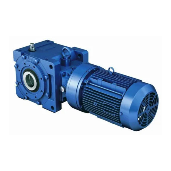
Bevel buddybox
right angle spiral bevel gearbox
with cyclo reducer input
Hide thumbs
Also See for Cyclo BBB4:
- Operation and maintenance manual (66 pages) ,
- Quick start manual (32 pages) ,
- Quick start manual (21 pages)

Related Manuals for Sumitomo Cyclo BBB4


Summary of Contents for Sumitomo Cyclo BBB4
- Page 1 Cyclo® BBB4 Bevel Buddybox® Right Angle Spiral Bevel Gearbox with Cyclo® Reducer Input Operation and ration and Maintenance Manual Manual 13.604.60.001...
-
Page 2: Table Of Contents
Cyclo® BBB4 Table of Contents Important Notes ......2 Models CMB-20 Brakes ..... . . 34 Safety Symbols . -
Page 3: Important Notes
Review and adhere to the instructions in this manual to ensure: Read this manual and all accompanying documents thoroughly before use. Understand the machine, information on safety, and all precautions for correct operation. Sumitomo recommends that this manual is easily accessible for reference at the machine location. -
Page 4: Delivery
Upon receipt of the reducer/gearmotor, verify that: purchase order Please consult your Sumitomo agent, distributor, or sales office if you find any defects or if you have any questions. Nameplate Inspection When contacting Sumitomo about this product, please be... -
Page 5: Nomenclature
Cyclo® BBB4 Nomenclature Nomenclature Our nomenclature details specific information about our proucts. Verify that the nomenclature of the unit delivered matches your order. Mounting Style Output Shaft Orientation Type Prefix Type Prefix Shaft Mount (Hollow Shaft) Horizontal Housing Vertical Flange (Solid Shaft) Vertical Up (Solid Shaft) Foot (Solid Shaft) Input Connection... - Page 6 Cyclo® BBB4 Nomenclature, continued Nominal and Exact Ratio BBB with Planetary Input BBB with Cyclo Input Nominal Ratio Frame Exact Single Reduction Input Overall Size Ratio Nominal Ratio Frame Exact Output Shaft Direction 4A10 10.50 Size Ratio Input Overall 4A12 21.0 4A14 10.89...
-
Page 7: Storing And Transporting
Cyclo® BBB4 reducer and the air vent is eyebolts. replaced with a sealing plug before shipping the reducer from Sumitomo factory. External machined surfaces are coated with a suitable NP-19 [JIS] petroleum base corrosion preventative such as Black Bear Par-Al-Ketone, Houghton Rust Veto 342, Daphne Ever Coat No.1 or equivalent. -
Page 8: Installation Notes
Consult your local distributor, Original Equipment Manufacturer the unit; fire may occur. or Sumitomo directly if the mounting angle is to be other than horizontal or vertical. prohibit proper ventilation. Inadequate ventilation may lead to high unit temperature and/or fire. -
Page 9: Installation Onto Driven Shaft
Taper-Grip® Bushing Introduction The keyless Taper-Grip® bushing system provides a simple and reliable shaft attachment for Sumitomo speed reducers and gearmotors. This system allows bi-directional shaft rotation operation with a powerful, slip-free grip. To assure peak performance of your equipment, please read, understand and follow these installation instructions. - Page 10 Cyclo® BBB4 Installation onto Driven Shaft, continued Taper-Grip® Bushing Loosen socket head cap screws. Remove (unscrew) Taper-Grip® bushing from the unit. Clean Driven Shaft Clean all grease, oil and/or anti-seize grease from the driven shaft. Failure to do so could result in damage to shaft. Slide Taper-Grip®...
- Page 11 Cyclo® BBB4 Installation onto Driven Shaft, continued Taper-Grip® Bushing Remove Taper-Grip® bushing from driven shaft. Do not apply anti-seize grease to the female threads in the hub. Apply a thin layer of anti-seize grease to the male threads of the Taper-Grip® bushing only.
- Page 12 Cyclo® BBB4 Installation onto Driven Shaft, continued Taper-Grip® Bushing Feeler Gauge Bushing Screw Bolts into Taper-Grip® bushing. Flange maintain the 1 mm (approximate) gap between the thrust collar and the bushing flange. Thrust Collar Tighten bushing bolts to the correct torque value. gradually tighten each socket head cap screw in 20% increments.
-
Page 13: Keyed Hollow Bore
Note: If the fit is tight, use a jig such as the one shown in Table 3 to ease assembly. Sumitomo does not supply a mounting jig. This information is provided for reference only. - Page 14 Cyclo® BBB4 Installation onto Driven Shaft, continued Keyed Hollow Bore (mm) Spacer b Nut d Threaded Rod e Size Bearing Threaded Rod 51104 M16 x 250 51105 M20 x 300 51105 M20 x 300 51107 M24 x 400 Ball Bearing 51107 M24 x 400 Retaining Ring a...
-
Page 15: Shrink Disc Type Hollow Bore
Shrink Disc Type Hollow Bore Shrink Disc Type Mounting Introduction The keyless Shrink Disc provides a reliable commodity shaft attachment for Sumitomo speed reducers and gearmotors. This system allows bi-directional shaft rotation operation with a powerful, slip-free grip. To assure peak performance of your equipment, please read, understand and follow these installation instructions. - Page 16 If the fit is tight, use a jig such as the one shown in the Keyed Hollow Bore Installation section to ease assembly. Sumitomo does not supply a mounting jig. This information is provided for reference only.
-
Page 17: Torque Arm Installation
The torque arm must be mounted in tension when torque arm mounting point is greater than 6 inches (150mm) from machine mounting point or, tie-rod or turn buckle type torque arm is used. Sumitomo Supplied Components of Torque Arm Components Item Number Description... - Page 18 Cyclo® BBB4 Torque Arm Installation, continued Torque Arm Bolt Place washer and rubber bushing on bolt. Rubber Insert torque arm bolt (supplied by customer) through mounting tab on Banjo Bushing torque arm. Washer When installed, bolt must be parallel to this Make sure bolt is parallel to Flange Mount (Banjo) Type Torque Arm surface surface when fully installed.
-
Page 19: T-Type Torque Arm
Cyclo® BBB4 Torque Arm Installation, continued T-Type Torque Arm T-Type Torque Arm Sumitomo Supplied Components for T-Type Torque Arm Table 8. T-Type Torque Arm Components Item Number Description Torque Arm Bracket Bracket Hardware Rubber Bushing (qty 3) Washer (qty 2) T-Type Torque Arm Installation Procedure Attach the T-Type Torque Arm Bracket to the Cyclo®... - Page 20 Cyclo® BBB4 Torque Arm Installation, continued T-Type Torque Arm Confirm that the rubber bushings can still be rotated by hand. This indicates the bushing has not been over tightened. Compressed bushings will not allow the bushings to properly absorb the loads of the shaft mounted gearbox.
-
Page 21: Removal From Driven Shaft
Cyclo® BBB4 Removal from Driven Shaft Removal of Cyclo® BBB4 with Taper-Grip® Bushing Removal of Cyclo® BBB4 with Taper-Grip® Bushing Before starting unit removal process, ensure that electrical power to unit has been safely locked out and that electrical connections to the unit have been disconnected. -
Page 22: Cyclo® Bbb4 With Keyed Hollow Bore
If shaft removal is difficult, a jig such as the one shown shown in Table 10 may be used to ease the removal process. Sumitomo does not supply the removal jig . This information is supplied for reference only. -
Page 23: Cyclo® Bbb4 With Shrink Disc
If shaft removal is difficult, a jig such as the one shown in the Removal of Cyclo® BBB4 with Taper-Grip® Bushing section may be used to ease the removal process. Sumitomo does not supply the removal jig. This information is supplied for reference only. -
Page 24: Lubrication
Lubrication Introduction, Lubrication Nomenclature Lubrication Introduction Sumitomo Cyclo® BBB4s units are shipped from the factory without lubricating oil, unless the customer specified otherwise when the unit was ordered. The unit must contain the correct type and amount of lubrication before operating. -
Page 25: Lubrication Method
Cyclo® BBB4 Lubrication, continued Lubrication Method Lubrication Method Using the model number and mounting configuration, refer to Tables 11 and 12 to determine the unit’s lubrication method. Table 11. Lubrication Method for Configurations Y1, Y2, Y3, Y5, Y6 Unit Size Mounting Configuration Lubrication Method Bevel Gear... -
Page 26: Bevel Gear Portion And Cyclo® Portion Recommended Oils . 25 Cyclo® Portion Recommended Greases
Shell Gadus S2 V220 NLGI 00 14° – 122°F (-10º – 50ºC) 19:1 and higher ExxonMobil Unirex N2 grease Cyclo portions have unique operating characteristics that require specific lubricant properties. Please consult Sumitomo if alternate lubricants are required. Cyclo® BBB4 Operation & Maintenance Manual... -
Page 27: Oil Quantities
Cyclo® BBB4 Lubrication, continued Oil Quantities Oil Quantities Table 16. Single Reduction Approximate Oil Quantity Units: US liquid gallon (liter) Note: Output = Bevel Gear Portion Input = Cyclo® Portion Mounting Configuration Bevel Gear Unit Size Output Input 4A10 0.4 (1.62) 0.8 (3.17) 0.4 (1.36) 0.5 (1.84) -
Page 28: Oil Supply Procedure
Cyclo® BBB4 Lubrication, continued Oil Supply and Discharge Procedures Oil Supply Procedure not necessary. Check the oil level when the unit is stopped to ensure that it has the correct amount of oil. lubrication provider’s oil analysis recommendations to ensure reducer performance. products is necessary for proper overhaul. -
Page 29: Grease Quantities
Cyclo® BBB4 Lubrication, continued Grease Quantities Grease Quantities The Cyclo® (input) portion of only Y4 double reduction units is grease lubricated at the factory. Additional grease is not required before initial start-up. All assemblies other than Y4 have oil lubricated Cyclo® portions. The following tables are provided for user rebuild or refurbishment reference. -
Page 30: Grease Replenishment And Draining Procedures
Cyclo® BBB4 Lubrication, continued Grease Replenishment and Draining Procedure, Grease Replacement Grease Replenishment and Draining Procedure 1. Remove the grease discharge plug from the outside cover. 2. Add grease with a grease gun from the grease nipple in the inside cover section or motor connection cover. 3. -
Page 31: Motor Wiring
Wiring Guidelines This section details wiring for standard Sumitomo three-phase motors and brakemotors. If using a motor manufactured by a company other than Sumitomo, please refer to that manufacturer’s instruction manual for wiring, operating and maintenance details. When wiring motors into the power supply, Sumitomo recommends the use of terminal rings to facilitate the connection: Figure 2. -
Page 32: Motor Protection
Cyclo® BBB4 Motor Wiring, continued Motor Protection, Motor Wiring Method Motor Protection U.S. Standard Motors Table 24. Typical 230/460V, Three-Phase Wiring Configuration by Motor Type Motor Wiring Method Motor Duty Motor HP (kW) x P Standard CSA AF-Motor AF-Motor 1/8 (0.1) x 4 plate. -
Page 33: Brake Wiring
40 (30) x 4 Brake Wiring Varistor Selection For wiring of Fast Brake Action, Sumitomo recommends the use of a Varistor (VR). Refer to Table 26 to assist in the selection of the appropriately sized Varistor. Table 26. Varistor Specifications Table... -
Page 34: U.s. Standard And Csa Approved Motor Brake Wiring
Figure 13. Normal Brake Action, 230V, 460V Figure 14. Fast Brake Action, 230V, 460V Power Module Brake Power Module Brake Furnished by Sumitomo Furnished by Sumitomo AC LINE AC LINE Note: [1] Refer to Varistor Specifications Table Cyclo® BBB4 Operation & Maintenance Manual... -
Page 35: Models Cmb-20 Brakes
Figure 15. Normal Brake Action, 230V Figure 16. Fast Brake Action, 230V Motor Rectifier Brake Motor Rectifier Brake Furnished by Sumitomo Furnished by Sumitomo Line 208/230V Line 208/230V Figure 17. Normal Brake Action, 460V Figure 18. Fast Brake Action, 460V Motor Rectifier... -
Page 36: Ce Motor Brake Wiring
Figure 22. Fast Brake Action, 220V Motor 220V Brake Motor Rectifier Brake Motor Rectifier Brake Furnished by Sumitomo Furnished by Sumitomo 220VAC 220VAC CE-FB-SM-HIT-N Figure 24. Fast Brake Action, 380V Motor, 220V Brake, Tapped Figure 23. Normal Brake Action, 380V Motor, 220V Brake, Tapped... -
Page 37: Ce Motors Models Fb-01A Through Fb-15B With Inverter
Figure 27. Normal Brake Action, 380V Motor, 380V Brake Figure 28. Fast Brake Action, 380V Motor, 380V Brake Motor Rectifier Brake Motor Rectifier Brake Furnished by Sumitomo Furnished by Sumitomo 380VAC 380VAC CE Motors Models FB-01A through FB-15B with Inverter CE-FB-VF-F CE-FB-VF-N Figure 29. Normal Brake Action Figure 30. -
Page 38: Brake Rectifiers And Power Modules
Cyclo® BBB4 Motor Wiring, continued Brake Rectifiers and Power Modules Brake Rectifiers and Power Modules Table 28. Standard Brake Rectifiers 230V/460V Rectifier 575V Rectifier Motor Brake Type HP (kW) x P Model Number Part Number Model Number Part Number FB-01A 1/8 (0.1) x 4 1/4 (0.2) x 4 FB-02A... -
Page 39: Parts
Cyclo® BBB4 Parts Cyclo® BBB4 Reducer Figure 31. Cyclo® BBB4 Reducer Parts Table 31. Cyclo® BBB4 Reducer Parts Number Description Number Description BBB4 Gear Assembly Cyclo® High-Speed End Shield Cyclo® Ring Gear Housing Pins Eccentric Key Cyclo® Ring Gear Housing Rollers High Speed Shaft Oil Seal Collar Cyclo®... -
Page 40: Cyclo® Planetary Reduction Component Parts (Cyclo® Ratios 11 - 18:1)
Cyclo® BBB4 Parts, continued Cyclo® Planetary Reduction Component Parts Figure 32. Cyclo® Planetary Reduction Component Ring Gear Bevel Shaft Pin Carrier Planet Gears Sun Gear Cyclo® Planetary Reduction Part Numbers Unit Size Cyclo® Reduction Block Set Bevel Shaft Overall Planet Gear Ring Gear Sun Gear Unit Size... -
Page 41: Cyclo® Reduction Component Parts (Cyclo® Ratios ≥ 19:1)
Cyclo® BBB4 Parts, continued Cyclo® Reduction Component Parts Figure 33. Cyclo® BBB4 Reduction Components - 4A100 thru 4F195 Bevel Pin Carrier Reduction Kit Input Kit Reduction Ratio Part Numbers Reduction Ratio Part Numbers Unit Size Unit Size Reduction Bevel Pin Reduction Bevel Pin Overall... - Page 42 Cyclo® BBB4 Parts, continued Cyclo® Reduction Component Parts continued Reduction Ratio Part Numbers Reduction Ratio Part Numbers 4A12 4B12 4A14 4B14 4C14 Unit Unit Input Reduction Input Reduction Size Size Overall Cyclo® Overall Cyclo® Bevel Pin Bevel Pin Bevel Pin Bevel Pin Bevel Pin Carrier...
-
Page 43: Bearings And Oil Seals
Cyclo® BBB4 Parts, continued Bearings and Oil Seals Bearings and Oil Seals Figure 34. Cyclo® BBB4 Bearings and Oil Seals Table 34. Cyclo® BBB4 Reducer Bearings and Oil Seals Bearings Oil Seals Unit Size 4A100 4A105 32011 6302RSH2 6302Z 4A110 20 x 35 x 7 4A115 32017... -
Page 44: Bevel Gearing Parts And Tooth Count
Cyclo® BBB4 Parts, continued Bevel Gearing Parts and Tooth Count Bevel Gearing Parts and Tooth Count Bevel gear and pinions are sold in sets only. Individual components are not available for purchase. The information below regarding tooth count of the bevel gearset is provided for vibration analysis purposes. Figure 35. -
Page 45: Cyclo® Bbb4 Screw Conveyor Options
Cyclo® BBB4 Screw Conveyor Options Components, Assembly Instructions Screw Conveyor Components Figure 36. Cyclo® BBB4 Screw Conveyor Components Table 37. Typical Cyclo® BBB4 Screw Conveyor Components Item Number Description Screw Conveyor Shaft Cover Plate Optional Packing Seal/Oil Seal Screw Conveyor Adaptor Optional Gland Cover Shaft Retaining Plate Screw Conveyor Assembly Instructions... - Page 46 If supplied, carefully insert the application appropriate sealing material into the bore of the screw conveyor adapter. screw conveyor adapter, Sumitomo provides − High-Performance Braided Cord: recommended for use if the conveyed material is abrasive.
- Page 47 Cyclo® BBB4 Screw Conveyor Options, continued Assembly Instructions If using the braided cord seal, tighten the gland cover bolts to achieve appropriate sealing on the screw conveyor shaft. Gland Cover Bolts Operation & Maintenance Manual Cyclo® BBB4...
-
Page 48: Cyclo® Portion Disassembly/Assembly
Cyclo® Portion – General Disassembly Before starting the disassembly process, Sumitomo recommends draining and properly disposing of all lubrication. Carefully remove the entire Cyclo® BBB4 from the driven shaft by following the instructions outlined in the Removal From Driven Shaft section of this manual. - Page 49 Cyclo® BBB4 Cyclo® Portion Disassembly/Assembly, continued Disassembly Procedure Remove all bolts While continuing to externally support the entire Cyclo® BBB4 unit, remove each of the bolts from the Cyclo® ring gear housing (shown in horizontal position for clarity). Cyclo® Reduction Components Carefully separate the bevel gear housing assembly from the Cyclo®...
- Page 50 Cyclo® BBB4 Cyclo® Portion Disassembly/Assembly, continued Disassembly Procedure Using both hands, carefully remove the top Cycloid disc. Cycloid Disc Cycloid Disc Spacer For Cyclo® units supplied with a spacer, remove the Cycloidal disc spacer. Eccentric Bearing Remove the eccentric bearing from the high speed shaft. Using both hands, carefully remove the remaining Cycloid disc.
- Page 51 Cyclo® BBB4 Cyclo® Portion Disassembly/Assembly, continued Disassembly Procedure Ring Gear Housing Remove the ring gear housing Snap Ring Remove the spacer and the snap ring from the high speed end shield. Spacer High Speed Shaft Bearing Remove the high speed shaft, along with its associated bearing, from the high speed end shield.
-
Page 52: Cyclo® Portion - General Reassembly
Cyclo® BBB4 Cyclo® Portion Disassembly/Assembly, continued Reassembly Procedure Cyclo® Portion – General Reassembly The Cyclo® portion of the speed reducer may be reassembled by reversing the disassembly procedure. All parts must be returned to the original order from which they were removed during disassembly. Take care to keep the moving reduction components free of dust or foreign material, and properly align all gaskets in order to keep the assembly oil tight/leak free. - Page 53 Cyclo® BBB4 Cyclo® Portion Disassembly/Assembly, continued Reassembly Procedure Code on upper disc Insert the top Cycloid disc so that the code engraved on its surface is 180° opposed to the corresponding etched code on the lower Cycloid disc. 180 º Code on lower disc If the Cyclo®...
-
Page 54: Troubleshooting
Cyclo® BBB4 Troubleshooting Reducer Troubleshooting Reducer Troubleshooting This troubleshooting guide provides assistance in identifying and overcoming common problems with reducers and motors. If a problem with the reducer and/or the motor is not listed below, please consult the factory for assistance. Reducer Troubleshooting Problem with the Reducer Possible Causes... - Page 55 Cyclo® BBB4 Troubleshooting, continued Motor Troubleshooting Motor Troubleshooting Problem with the Motor Possible Causes Suggested Remedy Faulty switch contact Adjust the contact Blown fuse Replace fuse One phase wire of the power supply Makes a Rewire connection open “groaning” sound Stator coil open Repair by rewinding or replacing the stator assembly Load is...
- Page 56 Cyclo® BBB4 Notes Cyclo® BBB4 Operation & Maintenance Manual...
- Page 57 Cyclo® BBB4 Notes Operation & Maintenance Manual Cyclo® BBB4...
- Page 58 Argentina Japan Sumitomo Heavy Industries, Ltd. Buenos Aires Power Transmission & Controls Group SM-Cyclo de Argentina SA Shinagawa-ku, Tokyo 141-6025 Japan Area de Promocion el Triangulo, Partido Malvinas Argentinas Manual 13.604.60.001 ©2012 Sumitomo Machinery Corporation of America Printed in USA...
Need help?
Do you have a question about the Cyclo BBB4 and is the answer not in the manual?
Questions and answers