Table of Contents
Advertisement
Advertisement
Table of Contents

Subscribe to Our Youtube Channel
Related Manuals for Bentel B-TEL99


Summary of Contents for Bentel B-TEL99
- Page 2 BENTEL SECURITY reserves the right to modify the technical features of this product without prior notice. via Florida Z.I. Valtesino - 63013 GROTTAMMARE (AP) - ITALY Installation and Quick guide: DUAL CHANNEL TELEPHONE DIALLER B-TEL99 ISTRUZIONI AVVISATORE TELEFONICO B-TEL99 ISTB-TEL99...
-
Page 3: Table Of Contents
TABLE OF CONTENTS INTRODUCTION General features ..... . 5 Description ......6 Alarm cycle . - Page 4 Stop Alarm cycles via telephone ... . 31 Listen-in ......32 Telephone dialler B-TEL99...
-
Page 5: Introduction
Stop alarm cycle/s and Listen-in via remote telephone, by means of modifi- able User Command PIN. r Stop Alarm by means of modifiable User Command PIN on B-TEL99 key- pad. r 7 programmable telephone numbers for each channel. -
Page 6: Description
Phase 3 If the Dial-tone check is enabled (see "Dial-tone check" programming op- tion 7) the B-TEL99 will check for the dial tone, if the dial tone is detected the B-TEL99 will step to successive phase. If the dial tone is not detected (option enabled) the B-TEL99 will release the telephone line and step back to phase1. - Page 7 B-TEL99 will step to the successive phase. If, however, the Voice answer detection option is disabled, the B-TEL99 will wait 5 seconds after dialling, and then step to the successive phase.
-
Page 8: Technical Features
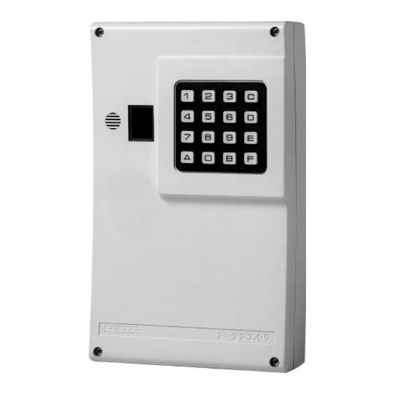
Pulse length for alarm channels (L1 and L2) 0.3 s Tamper line 500 mA - 24 V Pause between successive calls Pause between call attempts 60 s Dimensions (W*H*D) 132*220*62 mm Weight (without battery) 1.2 Kg Figure 2 Front panel parts. Telephone dialler B-TEL99... -
Page 9: Parts
Parts PART N. DESCRIPTION Screws (4) to secure front panel to backplate. Microphone for message recording. LED display. Alphanumeric telephone type keypad. Holes (4) for backplate mounting (Ø 5 mm). Loudspeaker for message playback. Compartment for 12 V, 1.2 Ah battery (not supplied). Cable passage (Ø... - Page 10 PART N. DESCRIPTION Reset button. Tamper switch. Connection terminal board. Loudspeaker connection. Jumper for activation mode setting: > actuated by positive drop (default) ; > actuated by negative command. Figure 4 PCB parts. Telephone dialler B-TEL99...
-
Page 11: Installation
Ø To allow easy access to the keypad and microphone, and for an adequate view of the display, the B-TEL99 should be installed at a height of about 160 Ø Before drilling the stop holes, check for water pipes and electrical cables. - Page 12 Tamper. These normally closed terminals must be connected to the tam- per switch/es 13 (on-board), and 11 (not supplied). The tamper switch 13 opens the circuit when the front panel of the B-TEL99 is removed. The op- tional tamper switch 11 (installed on the backplate, by request) opens the circuit when the B-TEL99 is pulled off the wall.
-
Page 13: Basic Connections
Terminal 10[OUT] is an open-collector output (NPN). Device The B-TEL99 has two Alarm channels. Alarm channel 2 can be used for connection the connection to the alarm relay of the fire alarm system, to the Duress re- lay of the security system, or for the connection of a radio receiver (tele- service). - Page 14 (a terminal with Negative when the system is armed), or to terminal [+OFF] of the Burglar system (a terminal with Positive when the system is dis- armed). In the latter case, a 1k5, 1/4 W resistance between terminal [B.A.] and [ Figure 5 Basic and auxiliary connections. Telephone dialler B-TEL99...
-
Page 15: Programming
PROGRAMMING All the B-TEL99 parameters must be set during the programming phase. The parameters can be set according to installation and user require- ments. The parameters are: r Installer PIN r Telephone numbers r Alarm mes- sages r User Command PIN r Message management r Number of call cy- cles r Message playback time r Dialling type (DTMF or Pulse) r Dial-tone check r Voice answer detection r Dial-tone type. -
Page 18: Programming Chart
Programming chart The programming chart on the previous two pages will help the installer plan and carry out programming of the B-TEL99 dialler. The chart serves as a programming guide, as it shows (for each parameter) the keys to press (KEY column) the value to enter (DESCRIPTION column) and the factory default (DEFAULT column). -
Page 19: Installer Pin: Access To The Programming Phase
Installer PIN: Access to the programming phase To access the programming phase of the B-TEL99, open the control panel and press 12 on the board, or enter the default Installer PIN 11 and press The display 4 will show the symbol thus indicating ready status: enter the required parameters. -
Page 20: Telephone Numbers
Telephone numbers The B-TEL99 can store 7 telephone numbers for each alarm channel: each number can have up to 15 digits and one or more pauses of 1 and/or 5 sec- onds (e.g. between the area code and the phone number). -
Page 21: Alarm Messages
A Short Common Message (16 seconds) for both alarm channels + 2 brief dedicated messages (8 seconds per message), one for each alarm chan- nel (see "OPTIONS"). Default setting The B-TEL99 message memory is empty (no default setting). Figure 6 Alarm message: graphic illustration (see option n. 1) PROGRAMMING... -
Page 22: Long Common Message - Short Channel 1 Message - Brief Dedicated Channel 1 Message
0 - 9 - 8 and so forth (0 stands for 10). Playback To playback the alarm channel 1 message proceed as follows: è Access the programming phase ... è Press è Press to select the alarm channel 1message. Press to start playback. Telephone dialler B-TEL99... -
Page 23: Alarm Channel 2 Short Message - Brief Dedicated Channel 2 Message
User Command PIN The User Command PIN can stop the programmed B-TEL99 call cycle/s during an alarm status, and can be used on the B-TEL99 keypad and on the kepad of the telephone called by B-TEL99 (see "Stop Alarm"). Default setting The B-TEL99 default PIN is 22. -
Page 24: Options
(32 seconds) to both alarm channels. Ø Value [2] = Two Dedicated Messages When 2 is selected the B-TEL99 will assign a Dedicated Message to each alarm channel (16 seconds per message). Ø Value [3] = Short Common Message + 2 brief dedicated messages... -
Page 25: Option 2) Number Of Call Cycles
1 (priority channel), the remaining alarm channel 2 cycles will re- start when alarm channel 1 cycles end. The B-TEL99 may be programmed to carry out 1, 2, 3, 4 or 5 call cycles. Default setting The default setting is 4 call cycles. -
Page 26: Option 3) Message Playback Time
Option 4) Dialling type It is possible to select pulse or DTMF dialling, according to the local dialling type, however, when possible select DTMF as it is faster than pulse dialling. Default setting The default setting is for DTMF. Telephone dialler B-TEL99... -
Page 27: Option 5) Dial-Tone Check
Option 5) Dial-tone check When this option is disabled, the B-TEL99 will dial the numbers, assigned to the alarm channel in alarm status, without checking for the dial tone. If, however, this option is enabled, the B-TEL99 will dial the programmed... -
Page 28: Option 6) Voice Answer Detection
For example, if alarm channel 2 goes into alarm status, and is set for 3 call cycles, the B-TEL99 will call the first enabled telephone number assigned to alarm channel 2. With this function mode, if the first telephone number dialled is successful it will not be dialled during the successive call cycle. -
Page 29: Option 7) Dial-Tone Type
è Press to confirm and quit. Activation mode By means of the jumper 16 it is possible to program B-TEL99 activation by positive drop or negative command. Default setting The default setting is activation by positive drop. To set the activation mode proceed as follows: Ø... -
Page 30: Logger
Clear Logger To clear the event logger during viewing: press twice; the logger will be cleared completely, and the B-TEL99 will step back to the programming phase. If access to the empty logger is requested will be shown on the display. -
Page 31: Quick Guide
ATTENTION In the event of an alarm status, all telephone devices con- nected after the B-TEL99 will be isolated until the end of the programmed call cycle/s. When the alarm cycles end or are stopped, the telephone line will be released. -
Page 32: Listen-In
Listen-in time. Auxiliary The B-TEL99 has an auxiliary command which stops the alarm cycle/s, this can be connected to an electric lock, burglar control panel, radio re- ceiver or other similar devices. The installer will enable this command if re- quired.
Need help?
Do you have a question about the B-TEL99 and is the answer not in the manual?
Questions and answers