
Related Manuals for WÄRTSILÄ LAZ 5100


Summary of Contents for WÄRTSILÄ LAZ 5100
- Page 1 NAVIGATION ECHO SOUNDER LAZ 5100 / ES 5100 Technical Manual TH 52 603 8001 EN Original instructions Store safely for subsequent use!
-
Page 3: Technical Manual Laz 5100 / Es
Technical Manual LAZ 5100 / ES 5100 Foreword Wärtsilä ELAC Nautik GmbH manufactures state-of-the-art quality products. In order to ensure the intended, correct and successful use of the products manufactured by Wärtsilä ELAC Nautik GmbH throughout the entire service life of the product, certain information and knowledge is necessary in corresponding phases of the product life, as described in this document. -
Page 4: General Information 1
Technical Manual LAZ 5100 / ES 5100 Foreword Documentation Specifications Upon publication of the present revised version, all previous editions become invalid. Designation Details/Data Description Documentation number TH 52 603 8001 EN Publication date 06/2016 Month/Year Current revision status of the documentation. - Page 5 Technical Manual LAZ 5100 / ES 5100 Foreword List of Changes and Supplements Revision Content Page(s) Changed by Date Name changed to LAZ 5100 / ES Cover and L3 ELAC 5100. Appendix with documents for 02/2011 chapter 7 NAUTIK LAZ 5100 and ES 5100...
- Page 6 Technical Manual LAZ 5100 / ES 5100 Foreword Technical Manual LAZ 5100 / ES 5100 TH 52 603 8001 EN Rev.: S...
-
Page 7: Table Of Contents
Technical Manual LAZ 5100 / ES 5100 Table of Contents TABLE OF CONTENTS 1 GENERAL INFORMATION ..................... 1-1 1.1 Purpose of the Document ....................1-1 1.2 Target Audience / Personnel Qualifications ..............1-1 1.2.1 Target Audience ....................... 1-1 1.2.2 Personnel Qualifications ....................1-1 ... - Page 8 Technical Manual LAZ 5100 / ES 5100 Table of Contents 4 OPERATING INSTRUCTIONS ..................4-1 4.1 Switching the System On/Off ................... 4-1 4.2 Brief Explanation of Control Keys ..................4-2 4.3 Display Area ........................4-3 4.3.1 Single Channel Display ....................4-3 ...
-
Page 9: General Information
Navigation Echo Sounder LAZ 5100 / ES 5100. The navigation echo sounders LAZ 5100 and ES 5100 are identical. The only difference lies in the name. For simplification the term navigation echo sounder or echo sounder is used in this manual for both versions, when an explicit distinction is not required. -
Page 10: Representational Conventions
Technical Manual LAZ 5100 / ES 5100 GENERAL INFORMATION Representational Conventions 1.3.1 Symbols and Notes The following section provides examples regarding the nature and design of symbols and (safety) instructions used in this documentation. 1.3.1.1 Examples for Symbols and Instructions Denotes general instructions and explanations. - Page 11 Technical Manual LAZ 5100 / ES 5100 GENERAL INFORMATION WARNING! Denotes dangerous electric voltage. WARNING! Denotes components posing an electrostatic hazard. WARNING! Denotes hot surfaces. WARNING! Denotes a potential environmental hazard. TH 52 603 8001 EN Rev.: S Technical Manual LAZ 5100 / ES 5100...
-
Page 12: Safety
Technical Manual LAZ 5100 / ES 5100 GENERAL INFORMATION Safety 1.4.1 General Products by Wärtsilä ELAC Nautik GmbH have been developed and manufactured in accordance to state of the art and the recognised technical safety regulations, and ensure a high operating reliability. -
Page 13: Obligations Of The Personnel
Technical Manual LAZ 5100 / ES 5100 GENERAL INFORMATION Obligations of the Personnel CAUTION! Hazard to working safety! Improper operation can endanger working safety! Installation measures must only be carried out by appropriately trained personnel! All personnel who perform work on or with the system as described in this documentation shall undertake, before any work begins: ... -
Page 14: Requirements For The Workplace
Technical Manual LAZ 5100 / ES 5100 GENERAL INFORMATION Requirements for the Workplace In addition to the mandatory national and company-specific regulations, safety and accident prevention regulations and recognised technical regulations applicable at the point of use, the following requirements for the workplace must be observed: ... -
Page 15: General Installation Instruction For Echo Sounders
Technical Manual LAZ 5100 / ES 5100 GENERAL INSTALLATION INSTRUCTION FOR ECHO SOUNDERS GENERAL INSTALLATION INSTRUCTION FOR ECHO SOUNDERS General Remark to Hydro Acoustic Equipment Even with a carefully selected transducer position and proper installation, the function of hydro acoustic equipment can be impaired by turbulence, acoustic noise or aerated water. -
Page 16: Cable Length, Operating Frequency
Technical Manual LAZ 5100 / ES 5100 GENERAL INSTALLATION INSTRUCTION FOR ECHO SOUNDERS 2.2.1 Cable Length, Operating Frequency Both the operating frequency and the length of cable between the echo sounder and the transducer influence the performance of echo sounding. -
Page 17: Cabling, Cable Location, Cable Specification
Technical Manual LAZ 5100 / ES 5100 GENERAL INSTALLATION INSTRUCTION FOR ECHO SOUNDERS 2.2.2 Cabling, Cable Location, Cable Specification When installing the connection cable, observe the following: Do not exceed permissible bending radius of the cables (see corresponding dimensional drawings)! ... -
Page 18: Transducer Cable Specification
Technical Manual LAZ 5100 / ES 5100 GENERAL INSTALLATION INSTRUCTION FOR ECHO SOUNDERS 2.2.3 Transducer Cable Specification The cable from the transducer connection box to the echo sounder must be approved marine cable (double screened). At least a resistance <13 Ω/km and a capacity of < 150 nF/km is required. -
Page 19: Installation Checkout (Installation Report / Service Request)
Technical Manual LAZ 5100 / ES 5100 GENERAL INSTALLATION INSTRUCTION FOR ECHO SOUNDERS 2.2.5 Installation Checkout (Installation Report / Service Request) 2.2.5.1 Installation Report After the installation and the quick check (see chapter 5.1.4) are completed, please fill in the installation report (see chapter 7.1) and send a copy to the Wärtsilä ELAC Nautik service centre (see chapter 2.2.5.3). - Page 20 Technical Manual LAZ 5100 / ES 5100 GENERAL INSTALLATION INSTRUCTION FOR ECHO SOUNDERS Technical Manual LAZ 5100 / ES 5100 TH 52 603 8001 EN Rev.: S...
-
Page 21: Technical Description
Technical Manual LAZ 5100 / ES 5100 TECHNICAL DESCRIPTION TECHNICAL DESCRIPTION General The Navigation Echo Sounder is a compact, processor controlled, state of the art system. Indication of the water depth is made on a Liquid Crystal (Colour) Display (LCD) as depth below the keel (DBK). -
Page 22: System Configuration
Technical Manual LAZ 5100 / ES 5100 TECHNICAL DESCRIPTION System Configuration 3.2.1 System Overview (with Options) The basic system configuration is as follows: 1 x Display and Control Unit 1 x Connection Box 1 x Transducer Navigation Echo... -
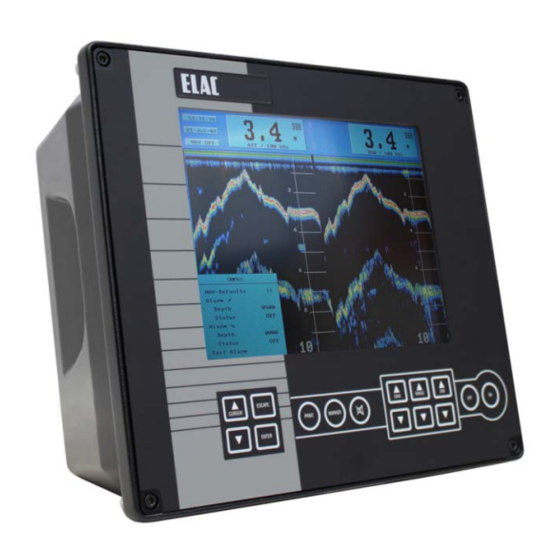
Page 23: Display And Control Unit
Technical Manual LAZ 5100 / ES 5100 TECHNICAL DESCRIPTION 3.2.2 Display and Control Unit The Display and Control Unit will normally be installed on the bridge, either mounted in a console or bracket mounted to the deckhead or bulkhead. It consists of a display area and a keypad which is used to alter system parameters and settings. -
Page 24: Optional Equipment
Technical Manual LAZ 5100 / ES 5100 TECHNICAL DESCRIPTION Optional Equipment The following optional equipment is available to enhance the system capabilities: Digital Slave Display(s) (see 3.3.1) Printer (see 3.3.2) Connection Box (see 3.3.3) Transducer(s) (see 3.3.4) ... -
Page 25: Transducer Options
Technical Manual LAZ 5100 / ES 5100 TECHNICAL DESCRIPTION 3.3.4 Transducer Options If the installed version is a dual channel version, the system is capable of accommodating two transducers without further modification, e.g. one fore and one aft, one port and one starboard. -
Page 26: Technical Data
Technical Manual LAZ 5100 / ES 5100 TECHNICAL DESCRIPTION Technical Data Designation Value 95 – 240 V AC, 50 - 60 Hz Supply voltage, nominal 10 - 30 V DC (option, via power pack) Power consumption Approx. 35 W Operating temperature range -15°C - +55°C... -
Page 27: Interfaces
Technical Manual LAZ 5100 / ES 5100 TECHNICAL DESCRIPTION Interfaces The Navigation Echo Sounder has the following interfaces: Monitor Printer RS 422 DAZ 25 2nd DAZ (Centronics Mute NMEA 0183 (Digital (Blanking, Parallel) Control ( NAV ) Slave via Conn. Box) -
Page 28: Description Of Nmea Interfaces
Technical Manual LAZ 5100 / ES 5100 TECHNICAL DESCRIPTION 3.5.1 Description of NMEA Interfaces All serial interfaces described in this chapter conform to EN 61162-1 (2001). 3.5.1.1 NMEA-Interface X4 A navigation system can be connected to this interface so that the ship's co-ordinates are displayed by the NAVIGATION ECHO SOUNDER. -
Page 29: Nmea-Interface X8
Technical Manual LAZ 5100 / ES 5100 TECHNICAL DESCRIPTION Example: $ZAZDA 184533.20 20,12,1995 12,15 62 <CR><LF> Checksum Difference 12 hrs 15 mins Date 20th Dec 1995 UTC=18:45:33.20 s Data are originating from an atomic clock 3.5.1.2 NMEA-Interface X8 Interface for START / STOP - SLAVE indicator, potential free alarm relay contacts and Digital Slave Indicator. - Page 30 Technical Manual LAZ 5100 / ES 5100 TECHNICAL DESCRIPTION $SDDBT 0012.1,f 0003.7,M 0002.0,F 32 <CR><LF> Checksum Depth = 2 fathoms Depth = 3.7 metres Depth = 12.1 feet 3-10 Technical Manual LAZ 5100 / ES 5100 TH 52 603 8001 EN Rev.: S...
- Page 31 Technical Manual LAZ 5100 / ES 5100 TECHNICAL DESCRIPTION ELA (Manufacture’s Mnemonic Code) A NMEA proprietary sentence by ELAC is available to allow the transfer of dual channel depth information, including transducer mounting position. $PELACSDS,k,x.x,d.d,-t.t,m,g,r*hh<CR><LF> Checksum Range Scale Depth quality...
-
Page 32: Description Of The Other Interfaces
Technical Manual LAZ 5100 / ES 5100 TECHNICAL DESCRIPTION To activate the Protocol ELAC see chapter 5.1.4 Initial System Set-Up. 3.5.2 Description of the other Interfaces 3.5.2.1 Interface X5 Mute Control Output (relay contact). 3.5.2.2 Interface X6 This interface provides a power supply and serial data output for a second Digital Slave Display and a blanking pulse output. -
Page 33: Pin Connections
Technical Manual LAZ 5100 / ES 5100 TECHNICAL DESCRIPTION 3.5.3 Pin Connections Input PC – Test **** Output 2 Printer Output 1 Monitor Mute VDR / DAZ 25 DAZ 25 X 38 NMEA – Depth – Out / CANL ***... -
Page 35: Operating Instructions
Technical Manual LAZ 5100 / ES 5100 OPERATING INSTRUCTIONS OPERATING INSTRUCTIONS CAUTION! Operating errors possible! The system must be operated by trained, qualified personnel only! Switching the System On/Off The transducer will be destroyed if operated out of water! ... -
Page 36: Brief Explanation Of Control Keys
Technical Manual LAZ 5100 / ES 5100 OPERATING INSTRUCTIONS Brief Explanation of Control Keys ESCAPE CURSOR GAIN RANGE PRINT MARKER ENTER Figure 4-2: Keypad Value The CURSOR keys allow the user to move the cursor within a MENU and alter parameters. The position of the cursor can easily... -
Page 37: Display Area
Technical Manual LAZ 5100 / ES 5100 OPERATING INSTRUCTIONS Display Area 4.3.1 Single Channel Display The Display Area is used to present all relevant information. The screen is divided into two areas. The lower, main area is used to present an echogram of the scenario beneath the ship. - Page 38 Technical Manual LAZ 5100 / ES 5100 OPERATING INSTRUCTIONS Figure 4-4: Single Channel Display The large window at the right-hand side of the information area is used to display the actual water depth, the measurement mode, units of measurement. The measurement mode can be either: ...
-
Page 39: Two Channel Display
Technical Manual LAZ 5100 / ES 5100 OPERATING INSTRUCTIONS 4.3.2 Two Channel Display In the two channel mode, information about location and frequency of the transducer in use is added. Figure 4-5: Two Channel Display If the presentation channel 1/2 is selected, Information of both channels is shown in a vertical split display. -
Page 40: Altering System Parameters And Settings
Technical Manual LAZ 5100 / ES 5100 OPERATING INSTRUCTIONS Altering System Parameters and Settings When the system is switched OFF, parameters selected are stored in the system's memory. When the system is switched ON again, these parameters will be retrieved and used (see NOTE below). -
Page 41: Range Settings
Technical Manual LAZ 5100 / ES 5100 OPERATING INSTRUCTIONS 4.4.1.2 RANGE Settings The RANGE can be set to suit the circumstances e.g. if a water depth of 35 m is indicated, the 50 m range will give a better resolution and accuracy than the 200 m range. -
Page 42: General Information Regarding Menus
Technical Manual LAZ 5100 / ES 5100 OPERATING INSTRUCTIONS 4.4.2 General Information Regarding Menus The ENTER key is used to call up the various MENUS in sequence. They appear in the following order: Press the ENTER key 1x : ALARM MENU ... -
Page 43: Altering System Settings/Parameters Within A Menu
Technical Manual LAZ 5100 / ES 5100 OPERATING INSTRUCTIONS 4.4.3 Altering System Settings/Parameters within a Menu When a MENU is called up, it will appear at the bottom left-hand side of the display area. There are 4 main MENUS available. These can be called up by pressing the ENTER key. - Page 44 Technical Manual LAZ 5100 / ES 5100 OPERATING INSTRUCTIONS The MENU below shows that the cursor has been moved down to mark the word "Depth" which now appears inverse. ALARM NAV-Defaults >> Alarm Depth Depth 0030 Status Alarm Depth 1990...
- Page 45 Technical Manual LAZ 5100 / ES 5100 OPERATING INSTRUCTIONS Press the ENTER key once more and the cursor will move to mark the word "Status" as shown in the MENU below: ALARM NAV-Defaults >> Alarm Depth 0020 Status Status Alarm...
- Page 46 Technical Manual LAZ 5100 / ES 5100 OPERATING INSTRUCTIONS Press the ENTER key and the cursor will move to the first digit of the alarm setting, in this case a 1, as shown in the MENU below. ALARM NAV-Defaults >>...
- Page 47 Technical Manual LAZ 5100 / ES 5100 OPERATING INSTRUCTIONS ALARM NAV-Defaults >> Alarm Depth 0020 Status Alarm Depth 0610 Status Test Alarm Figure 4-14: Alarm Menu Alter the Status to ON as described for the minimum depth alarm. Press the ENTER key to confirm.
-
Page 48: Menu Description
Technical Manual LAZ 5100 / ES 5100 OPERATING INSTRUCTIONS Menu Description 4.5.1 The ALARM Menu To call up the ALARM MENU, press the ENTER key once. ALARM NAV-Defaults >> Alarm Depth 0020 (0..1999m) Status (ON, OFF) Alarm Depth 0410 (0..1999m) -
Page 49: Nav-Defaults
Technical Manual LAZ 5100 / ES 5100 OPERATING INSTRUCTIONS 4.5.1.1 NAV-Defaults NAV (Navigation)-Defaults are basic compulsory settings which must be used when operating the system for navigational purposes. These are defined by the International Maritime Organisation (IMO) and state that: ... -
Page 50: The Parameter Menu
Technical Manual LAZ 5100 / ES 5100 OPERATING INSTRUCTIONS 4.5.2 The PARAMETER Menu To call up the PARAMETER MENU, press the ENTER key twice. PARAMETER Channel Select (1, 2, 1/2) Sound Velocity 1500 (1400..1699) Units (m, ftm, ft) Depth Mode... -
Page 51: Sound Velocity
Technical Manual LAZ 5100 / ES 5100 OPERATING INSTRUCTIONS 4.5.2.2 Sound Velocity Sound travels at varying speeds in water, depending upon salinity, temperature and density. The standard NAV (Navigation) default setting for sound velocity is 1500 m/s. If a sound velocity measuring system is available and the user wants to adjust the... -
Page 52: Depth Mode
Technical Manual LAZ 5100 / ES 5100 OPERATING INSTRUCTIONS 4.5.2.4 Depth Mode The standard default depth measurement mode is DBK (depth below the keel). It is however possible to change this mode to either DBT (depth below the transducer) or DBS (depth below the surface). -
Page 53: The Log Data Menu
Technical Manual LAZ 5100 / ES 5100 OPERATING INSTRUCTIONS 4.5.3 The LOG DATA Menu To call up the LOG DATA MENU, press the ENTER key three times. The MENU as shown below will appear. LO G DA TA Vi ew... -
Page 54: To View Stored Data
Technical Manual LAZ 5100 / ES 5100 OPERATING INSTRUCTIONS 4.5.3.1 To View Stored Data Call up the LOG DATA MENU as described previously. Press the CURSOR W key once to mark the word "VIEW", followed by the ENTER key. The MENU will disappear from the screen and stored data will appear. A typical Viewed Data display area is shown below. -
Page 55: Explanation Of Controls For Viewing Stored Data
Technical Manual LAZ 5100 / ES 5100 OPERATING INSTRUCTIONS 4.5.3.2 Explanation of Controls for Viewing Stored Data direction A direction B Reference line for information and setting print out time period limits Figure 4-21: Log Data Menu Controls for Viewing Data... -
Page 56: Scrolling Through Memory Data
Technical Manual LAZ 5100 / ES 5100 OPERATING INSTRUCTIONS 4.5.3.3 Scrolling through Memory Data To scroll the display to a certain time in the memory in order to view events that occurred earlier (relative to time shown in "time" window), press and hold the CURSOR W key until nearing the wanted time (shown in the "time"... -
Page 57: Printing Data From The Memory
Technical Manual LAZ 5100 / ES 5100 OPERATING INSTRUCTIONS 4.5.3.4 Printing Data from the Memory In order to make a print-out of all or part of the data stored in the memory, so called "limit markers" must be set. Only data within these limit markers will be printed. -
Page 58: The System-Setup Menu
Technical Manual LAZ 5100 / ES 5100 OPERATING INSTRUCTIONS 4.5.4 The SYSTEM-SETUP Menu WARNING! With the exception of time, date and colour, no other parameters must be altered unless modifications are made to the system, e.g. altering the installation depth of the transducer or replacing the transducer with one of a different frequency. -
Page 59: Changing The Date And Time
Technical Manual LAZ 5100 / ES 5100 OPERATING INSTRUCTIONS 4.5.4.1 Changing the Date and Time To change the system DATE, call up the SYSTEM SETUP MENU and press the following keys: CURSOR W (1x, to mark the word Date) ... -
Page 60: Color Bar Menu
Technical Manual LAZ 5100 / ES 5100 OPERATING INSTRUCTIONS 4.5.4.2 Color Bar Menu SYSTEM-SETUP Date 05.05.03 Time 12:34 Color Bar Service >> Version Version number and date Figure 4-23: System Set-Up Menu (Color Bar Menu) The Color Bar Menu allows user settings according to ambient conditions. Several combinations of echo indication and the overlay of general information are possible according to the following table. - Page 61 Technical Manual LAZ 5100 / ES 5100 OPERATING INSTRUCTIONS TH 52 603 8001 EN Rev.: S Technical Manual LAZ 5100 / ES 5100 4-27...
-
Page 63: Installation, Care And Maintenance
Technical Manual LAZ 5100 / ES 5100 INSTALLATION, CARE AND MAINTENANCE INSTALLATION, CARE AND MAINTENANCE WARNING! Danger for man and machine The operational safety of the system will be endangered if work is not carried out correctly and/or if unauthorised modifications are made! ... - Page 64 Technical Manual LAZ 5100 / ES 5100 INSTALLATION, CARE AND MAINTENANCE On ships equipped with a bulb bow, the transducer must be mounted as far as possible ahead, because the bulb generates a layer of air bubbles that heavily reduces the transducer / echo sounder performance.
-
Page 65: Transducer - Cable Connection
Technical Manual LAZ 5100 / ES 5100 INSTALLATION, CARE AND MAINTENANCE 5.1.1 Transducer – Cable Connection Figure 5-1 Instruction for transducer - cable connection TH 52 603 8001 EN Rev.: S Technical Manual LAZ 5100 / ES 5100... -
Page 66: Distortion Level Test
Technical Manual LAZ 5100 / ES 5100 INSTALLATION, CARE AND MAINTENANCE 5.1.2 Distortion Level Test After routing and connecting the transducer cable, a distortion level test must be carried out, to ensure the correct routing and screening of the transducer cables. -
Page 67: Transducer Types
Technical Manual LAZ 5100 / ES 5100 INSTALLATION, CARE AND MAINTENANCE 5.1.3 Transducer Types The transducers, listed in the table are samples, further types are available and can be connected to ELAC echo sounders. Maximum Transducer Electrical Maximum Frequency Manufacturer... -
Page 68: Initial System Set-Up
Technical Manual LAZ 5100 / ES 5100 INSTALLATION, CARE AND MAINTENANCE 5.1.4 Initial System Set-Up After installation of the Navigation Echo Sounder, please follow this procedure for setting into operation for the first time. Item Result Installation check Main supply (X3) Transducer (X1, X2) –... - Page 69 Technical Manual LAZ 5100 / ES 5100 INSTALLATION, CARE AND MAINTENANCE Once the system has been correctly installed, the initial set-up can be carried out. Call the SYSTEM SET-UP MENU by pressing the ENTER key four (4) times. When the SYSTEM SET-UP MENU appears on the display area, press the CURSOR W key three (3) times so that the word Service is highlighted as shown below.
-
Page 70: Power Adjust 5
Technical Manual LAZ 5100 / ES 5100 INSTALLATION, CARE AND MAINTENANCE Access to the SERVICE MENU is gained by pressing any CURSOR key. The word NO will change to YES. Press the ENTER key and the SERVICE MENU, shown below, will appear. -
Page 71: Care And Maintenance 5
Technical Manual LAZ 5100 / ES 5100 INSTALLATION, CARE AND MAINTENANCE The CHANNEL 1 MENU allows the service technician to set the following parameters: Draft: the transducer installation depth is entered here, i.e. the depth of the transducer below the waterline, e.g. 5.6 m. This compensation allows accurate surface to sea bed measurements. - Page 72 Technical Manual LAZ 5100 / ES 5100 INSTALLATION, CARE AND MAINTENANCE To alter the Blocking Depth setting, press the following keys: Call up the CHANNEL 1 SUB MENU as described previously CURSOR W (3x, to mark the word Blocking Depth) ...
- Page 73 Technical Manual LAZ 5100 / ES 5100 INSTALLATION, CARE AND MAINTENANCE In order to set or alter the parameters for Channel 2, call up the CHANNEL 2 MENU, as follows: Call up the SERVICE MENU as previously described CURSOR W (2x, to mark Channel 2) ...
- Page 74 Technical Manual LAZ 5100 / ES 5100 INSTALLATION, CARE AND MAINTENANCE To alter the External PC Mode, press the following keys: Call up the INTERFACES SUB-MENU as described previously CURSOR W (1x, to mark the word Mode) ENTER (1x, to mark the selected mode) ...
-
Page 75: Power Adjust
Technical Manual LAZ 5100 / ES 5100 INSTALLATION, CARE AND MAINTENANCE To alter the Protocol, press the following keys: Call up the INTERFACES SUB-MENU as described previously CURSOR W (6x, to mark the word Protocol) ENTER (1x, to mark the selected Protocol) ... -
Page 76: Care And Maintenance
Technical Manual LAZ 5100 / ES 5100 INSTALLATION, CARE AND MAINTENANCE Care and Maintenance The Navigation Echo Sounder is largely maintenance free. The transducer(s) should be cleaned whenever an opportunity arises, e.g. when the ship is in dock. The transducer(s) can be cleaned with a plastic scraper or scrubbing brush, see note below. -
Page 77: Applicable Documents
Technical Manual LAZ 5100 / ES 5100 APPLICABLE DOCUMENTS APPLICABLE DOCUMENTS Designation ELAC Document No. Comment Dimensional drawing MB 52 603 8001 Echo Sounder LAZ 5100 Installation drawing EZ 52 603 8001 Echo Sounder LAZ 5100 Circuit diagram SP 52 603 8001... - Page 78 Technical Manual LAZ 5100 / ES 5100 Applicable DOCUMENTS Technical Manual LAZ 5100 / ES 5100 TH 52 603 8001 EN Rev.: S...
-
Page 79: Appendix
Technical Manual LAZ 5100 / ES 5100 APPENDIX APPENDIX Installation – Report Installation – Report Schiffsname Ship’s name _________________________________________________ Installationsfirma Installation Company _________________________________________________ Installationsdatum Date of Installation ______________________________ LAZ 5100 ES 5100 Werk-Nr. (S/N) 1-Kanal – Gerät 2-Kanal – Gerät...
Need help?
Do you have a question about the LAZ 5100 and is the answer not in the manual?
Questions and answers