
Related Manuals for Auvidea J120

Summary of Contents for Auvidea J120
- Page 1 VERSION 1.9 J120 (38198-X) J120 technical reference manual 38198-X Version 1.9 Preliminary March 2018 Auvidea GmbH Kellerberg 3 D-86920 Denklingen Tel: +49 8243 7714 622 info@auvidea.com www.auvidea.com AUVIDEA GMBH TECHNICAL REFERENCE MANUAL...
-
Page 2: Copyright Notice
For any other mode of sharing, please contact the author at the email below. info@auvidea.com Commercial use and distribution of the contents of this document is not allowed without express and prior written consent of Auvidea GmbH. -
Page 3: Technical Details
• power: 12V typical (4 pin) - 2 power pins for redundant powering • range: 7V to 17V • do not use the 19V power supply of the Jetson TX1 dev kit - it will damage the J120 carrier board AUVIDEA GMBH... - Page 4 VERSION 1.9 J120 (38198-X) How do the various models differ? Feature J100 J100 + M100 J120 J130 J140 Jetson TX1 compatible ✓ ✓ ✓ ✓ ✓ HDMI out mini mini mini standard mini USB 3.0 type A micro USB 3.0 micro USB 2.0 OTG...
- Page 5 First revision of the J120. Very limited distribution. J120 Rev 2 (38198-2) Second revision of the J120. It became available in late April 2016. Modifications: • all 3 connectors on the left are aligned (Ethernet, USB3 and mini HDMI) • PCB size: 50 x 109.5 mm, total size: 50 x 110 mm •...
- Page 6 VERSION 1.9 J120 (38198-X) J120 rev 5 top side J120 rev 5 bottom side AUVIDEA GMBH TECHNICAL REFERENCE MANUAL...
- Page 7 (MS621FE-FL11E). It is located next to the power button. If the super cap and the Lithium cell are not populated, RTC power may be provided on the buttons connector (J12 pin 1). Testing of the J120 The following functions are tested: •...
-
Page 8: Getting Started
Console access The console port of the TX1 is UART 0. The J120 converts this UART port to standard 3.3V TTL levels. So a standard USB to TTL serial converter may be used to connect to the console. Just connect TXD, RXD and GND to the USB converter. - Page 9 CSI-2 connector The J120 features one CSI-2 connector with 4 data lanes. It is a 22 pin FPC connector with 0.5mm pitch. It has the same pin out as the 22 pin CSI-2 connector found on the carrier board for the Raspberry Pi compute module.
- Page 10 A 9 axis sensor is connected to the SPI0 bus of the TX1. Pin 8 (VddIO) of the IMU is connected to 1.8V. Please set the INT output of the IMU by software to „totem pole“ mode as there is no pull-up on the INT output. This IMU is optional. Only some J120 models are equipped with this function. Function...
- Page 11 70: -- -- -- -- -- -- -- -- The J120 features 1 or 2 CAN interfaces. As the Jetson TX1 does not have native CAN interfaces, the J120 features 2 SPI based CAN controllers (Microchip MCP2515). Please install the Kernel and support package with the MCP2515 driver, which is provided by Auvidea.
- Page 12 So M.2 type B (SATA) cards may fit mechanically, but they will not work. Please make sure that the M.2 card for the J120 has just one notch. Examples of M.2 type M SSDs with PCIe interface: •...
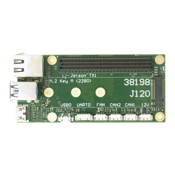
- Page 13 Auvidea supplies cable kits for the connectors with 1.25 mm pitch. Please check the website for details. Figure 1 and 2 show the J120 rev 2 but the connector placement and pin numbering also applies to the J120 rev 1.
- Page 14 VERSION 1.9 J120 (38198-X) USB 3.0 (J2) This is dual USB 3.0 type a connector. Pin 1-9 is the bottom connector and pin 10-18 is the top connector. Function Jetson TX1 Description 5V power controlled by USB2_EN_OC (A19) - max. 900 mA USB2-D- USB 2.0 data...
- Page 15 The two SPI to CAN controllers add two CAN bus interfaces to the TX1, as there is no internal CAN controller in the TX1. The SPI bus, RESET and INT are shared between the 2 CAN controllers (J120 rev 1). The J120 rev 2 will use separate SPI interrupts.
- Page 16 VERSION 1.9 J120 (38198-X) Function Jetson TX1 Description CAN1_L CAN data low Ground (0V) AUVIDEA GMBH TECHNICAL REFERENCE MANUAL...
- Page 17 CSI-2 bus E lane 1 Ground CSI-E-D0+ CSI-2 bus E lane 0 CSI-E-D0- CSI-2 bus E lane 0 Ground Ethernet (J1) The J120 features an on-board RJ45 connector for 10/100/1000BT Ethernet with 2 LEDs. Function Jetson TX1 Description GBE0 GBE_LINK_ACT* left LED GBE1 GBE_LINK_100...
- Page 18 This is a 6 pin connector with 1.25 mm pitch. Please connect to USB TTL serial converter (3.3V TTL level). Normally just connect TXD, RXD, and GND. Swap data lines. Default speed: 115200 bps. This is the configuration for the J120 rev 1 and J120 rev 2 with a serial number < 2021. Function...
- Page 19 UART 0 / UART 2 (J7) - rev 2 to 5 This is the configuration for the J120 rev 2 with a serial number > 2020. All 4 pins are passed through a bi- directional level converter with 3.3V level outputs (TXB0104PWR) and through 33 Ohm series resistors (in a tiny 0804 size resistor array).
- Page 20 VERSION 1.9 J120 (38198-X) Function Jetson TX1 GPIO Description 5V power output (3.3V if only the MCU is powered) UART0_TXD UART 0 console port (3.3V TTL level): transmit data output - tunnelled through the watchdog UART0_RXD UART 0 console port (3.3V TTL level): receive data input -...
- Page 21 I2C0_CLK (level shifted to 3.3V with 10k pullup) I2C0_DAT I2C0_DAT (level shifted to 3.3V with 10k pullup) Ground Note: J120 rev 1, 2, and 3: pin 8 and pin 9 have 1k pullup (rev 4 and newer: 10k) AUVIDEA GMBH TECHNICAL REFERENCE MANUAL...
- Page 22 Ground M.2 type M 2280 (J15) J120 rev 1: this slot is non functional due to power limitations of the integrated 3.3V power supply. J120 rev 2: this will be fixed by adding a 3.3V 3A power supply. Form factor: 2242, 2260 or 2280 (22 x 80 mm)
- Page 23 VERSION 1.9 J120 (38198-X) JTAG header (P1) This is a 9 pin connector with 1.25 mm pitch with surface mount pads on the edge of the board. Function Jetson TX1 Description 1.8V 1.8V power output JTAG_AP_TRST_L JTAG port of Jetson TX1...
- Page 24 VERSION 1.9 J120 (38198-X) The J90 features an on-board micro controller (MCU: STM32F042F6P6) with 32 kByte Flash and 6kByte RAM. MCU pin description MCU Pin Name Type Function Description PB8/BOOT0 10k pull down POWER 1: inactive, 0: press power button...
- Page 25 APPEND fbcon=map:0 console=tty0 console=ttyS0,115200n8 MCU firmware v1.3 This version of the MCU uses the standard baud rate of 115200 baud. The firmware is installed on the J120 rev 7 and newer. If your use case requires a direct connection to the UART0 of the TX1 and TX2 then there are the following options: 1.
- Page 26 2. please populate RN1 with a 10 Ohm resistor network (Panasonic: EXB-24V100JX, Digikey: Y5100CT-ND, Auvidea: 25151), to connect the UART0 port of the TX1/ TX2 to J7. Please note that this requires very good soldering skills and it should be performed by our technicians.
- Page 27 VERSION 1.9 J120 (38198-X) 1. to be added AUVIDEA GMBH TECHNICAL REFERENCE MANUAL...
- Page 28 VERSION 1.9 J120 (38198-X) Disclaimer Thank you for reading this manual. If you have found any typos or errors in this document, please let us know. This is the preliminary version of this data sheet. Please treat all specifications with caution as there may be any typos or errors.
Need help?
Do you have a question about the J120 and is the answer not in the manual?
Questions and answers