
Related Manuals for Infinity Solutions LMQ II


Summary of Contents for Infinity Solutions LMQ II
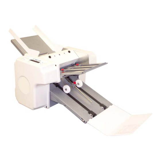
- Page 1 LMQ II Service Manual Infinity Solutions Manufacturing 192 Gannett Drive South Portland, ME 04106 (207) 899-1714...
-
Page 2: Table Of Contents
Table of Contents Table of Contents ...............................ii Tools Needed ..............................iii Machine Overview ..............................1 Chassis ................................1 Removing the Side Covers ..............................2 Removing the Motor Side Frame............................2 Servicing the Rolls ................................6 Drive Train ................................7 Removing the Drive Train Components..........................8 Feed Table ................................9 Servicing the Feed Drive System ............................ -
Page 3: Tools Needed
Tools Needed • Set of U.S.A. standard Inch Allen Wrenches (3/32”, 5/64”, 1/8”, 5/32”, 3/16”, ¼”) • 7/16” Deep Socket & Driver • ½” Open end wrench • Needle nose Pliers • Flat Head Screwdriver • Continuity Tester Before servicing the machine, disconnect the power cord from the machine. Warning:... -
Page 5: Machine Overview
Machine Overview Read the to become familiar with the machine operation. Operators Manual Feed Gauge Cover Upper Fold Feed Table Plate Paper Guides Lower Fold Plate Control Panel Electrical Panel Electrical Side Cover Feed Belts Motor Side Cover Conveyor Access Panel Conveyor Nip Wheel... -
Page 6: Chassis
Chassis Chassis Figure 1: Chassis Assembly View Removing the Side Covers Unplug the power cord from the machine before continuing. 1. Remove the four at the corners of Cover Mount Screws the side cover [Figure 2]. Removing the Motor Side Frame Cover Mount Screws Unplug the power cord from the machine before... - Page 7 down),resting it on the so that the side is seated properly in the side Electrical Side Cover Electrical Side Frame cover. 5. Remove the [Figure 6]. Conveyor Drive O-Ring 6. Remove the [Figure 6]. Feed Drive Belt 7. Remove the [Figure 6].
- Page 8 Chassis Feed Table Screws Feed Gauge Screws Feed Idler Slide Block Screws Rear Motor Guard Screw Motor Mount Screws Conveyor Mount Screws Front Motor Guard Screw Base Plate Screws Figure 3: Motor Side Frame Removal...
- Page 9 Control Panel Mount Screws Control Panel Circuit Board Circuit Board Mount Screws Power Switch / Breaker Main Circuit Board IEC Socket Drive Mounting Screws AC 3PH Drive Figure 4: Electrical Side Frame...
-
Page 10: Servicing The Rolls
Chassis Servicing the Rolls 1. Remove the [see section above]. Motor Side Frame 2. You will now be able to remove any roll that you need service [Figure 5]. Roll #2: Urethane Roll #4: Pulley End Roll #1: Urethane Conveyor Drive Shaft Roll #3: Hex End Figure 5: Servicing the Rolls... -
Page 11: Drive Train
Drive Train Feed Drive Belt Roll Gears Feed Pulleys Conveyor Belt Door Switch Conveyor Pulley Idler Gear Motor Gear Figure 6: Drive Train... -
Page 12: Removing The Drive Train Components
Chassis Removing the Drive Train Components Unplug the power cord from the machine before continuing. 1. Remove the [Figure 6]. Conveyor Drive O-Ring 2. Remove the [Figure 6]. Conveyor Pulley a. Loosen both set screws 2-3 turns. b. Pull the pulley off of the shaft. 3. -
Page 13: Feed Table
Feed Assembly Figure 7: Feed Assembly Servicing the Feed Drive System and Replacing the Feed Belts 1. Remove the [Figure 2]. Electrical Side Cover 2. Remove the from the [Figure 3]. Feed Idler Screws Electrical Side 3. Remove the from the [Figure 3]. - Page 14 Feed Table 13. Slide the back into the machine through the Frame, and through the Feed Drive Shaft Motor Side Feed Drive Roller. 14. Replace the on the E-Clips Feed Drive Shaft. 15. Replace the Feed Drive Pulley. Feed Drive Shaft Feed Idler Shafts Feed Drive Roller Feed Idler...
-
Page 15: Feed Gauge
Feed Gauge Figure 9: Feed Gauge Assembly Removing the Feed Gauge System and replacing O-Rings It is not necessary to remove either to remove the Side Frame Feed Gauge System. 1. Remove both [Figure 2]. Side Covers 2. Remove the [Page 1] Feed Gauge Cover 3. -
Page 16: Electrical
Electrical Electrical Disconnect from machine before servicing machine. Warning: Power Cord Replacing the Motor 1. Remove both [Figure 2]. Side Covers 2. Disconnect the from the Drive. Motor 3. Remove the and move the out of the way [Figure 4]. Drive Mounting Screws Drive 4. -
Page 17: Schematic
Figure 10: Wiring Schematic... -
Page 18: Conveyor
Conveyor Figure 1: Conveyor Assembly Servicing the Conveyor Disconnect the power cord from the machine before continuing. 1. Remove both from the machine [Figure 2]. Side Covers 2. Remove the from both side frames [Figure 3]. Conveyor Mount Screws 3. Remove the [see procedure above]. -
Page 19: Exploded Views
Exploded Views... - Page 29 ITEM PartNo DESCRIPTION QTY. 70-0220-00 Felt Holder 70-0221-00 Wiper Felt Strip 84-0164-00 Black #10-32 Thumb Screw UNLESS OTHERWISE SPECIFIED Bri-Lin Corporation ALL DIMENSIONS ARE IN INCHES 16 Amarosa Drive TOLERANCES: ANGLES Rochester, NH 03868 1 PLACE DECIMALS DRAWING TITLE 2 PLACE DECIMALS .010 WIPER ASSEMBLY 3 PLACE DECIMALS...
- Page 30 Phone (207) 899-1714 Phone (866) 427-4546 Fax (207) 228-1890 Fax (603) 332-8043 www.infinitysolutionsmfg.com www.brilininc.com...
Need help?
Do you have a question about the LMQ II and is the answer not in the manual?
Questions and answers