
Subscribe to Our Youtube Channel
Related Manuals for Infinity Solutions 7K Plus


Summary of Contents for Infinity Solutions 7K Plus
- Page 1 7K Plus Service Manual Infinity Solutions Manufacturing 192 Gannett Drive South Portland, ME 04106 (207) 899-1714...
-
Page 3: Table Of Contents
Table of Contents Table of Contents ..............................iii Service Manual Notes............................v Tools Needed..................................v Parts:....................................v Technical Help ................................... v Additional Notes................................. v 1. Machine Overview ............................6 1.1. Covers..................................7 2. Drive Train ...............................8 2.1. Conveyor Drive Pulley & O-Ring ..........................8 2.2. - Page 4 10.5.1 Misaligned Folds ................................26 10.5.2 Paper Feed Problems ................................ 26 10.5.3 Dirty forms..................................27 10.5.4 Motor Runs only in one direction............................27 10.5.5 Erratic speeds ........................Error! Bookmark not defined. 10.5.6 Excessive Noise................................. 27 10.5.7 Poor Stacking..................................27 10.6. Sensors ................................... 27 10.6.1 Doubles Detection................................
-
Page 5: Service Manual Notes
The majority of service operations are covered in this manual. However, if you are unable to resolve a problem please contact technical support at Infinity Solutions Manufacturing. Phone: (207) 899-1714 Additional Notes This manual is for use with the Infinity Solutions 7K plus. ... -
Page 6: Machine Overview
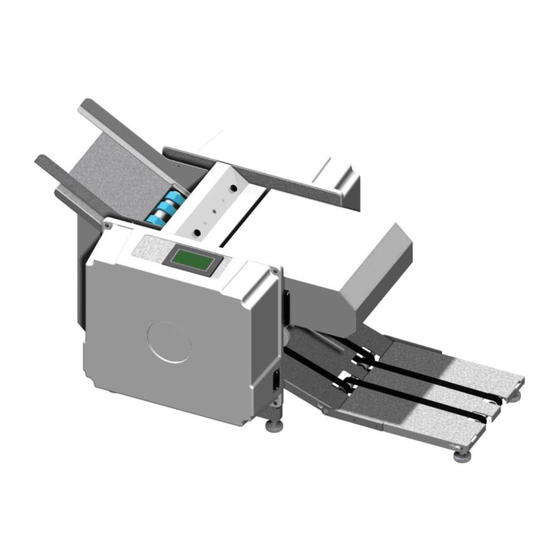
1. Machine Overview • Read the operators manual to become familiar with the machine operation. Feed Gauge Feed Table Control Panel Electrical Side Cover Motor Side Cover Conveyor Nip Wheels Extended Conveyor Upper Fold Plate Lower Fold Plate Figure 1: Overview... -
Page 7: Covers
Power Cord Plug Power Switch / Breaker Figure 2: Power Connection and Switch 1.1. Covers a) Removal 1. Remove the cover screws (4x). 2. Slide the cover off the machine. b) Installation 1. Installation is the reverse of removal. Cover Cover Screw (4x) Figure 3: Covers... -
Page 8: Drive Train
Roll Gears Feed Drive Feed Drive Belt Pulley Double Sided Belt Door Switch Feed Pinion Pulley Conveyor Pulley Motor Belt 28-0832-00 Motor Pulley and Clutch Figure 4: Drive Train Note: if motor belt is marked 5M450 15, then see addendum 2. -
Page 9: Drive Motor: Belt, Pulleys, And Clutch
Note: The conveyor pulley is mounted on a floating shaft and the pulley will self align itself, however is best if they are closely aligned to begin with. Tighten the set screw 3. Roll the o-ring onto the conveyor pulley. 4. - Page 10 Note: If improperly adjusted premature component failure or poor machine performance can occur. 1. Use a torque wrench to tighten the center nut of the clutch to 12 ft/lbs. 2. With the drive train completely assembled and all protective guards in place plug in the machine and power it 3.
-
Page 11: Double Sided Timing Belt And Drive Pulleys
2.3. Double Sided Timing Belt and Drive Pulleys a) Removal • Disconnect the power cord from the machine. 1. Remove the conveyor pulley, motor belt and the gears. (See Section 2.2) 2. Remove the double sided belt. a) Loosen the idler tension bracket and slide the bracket and pulley down to release tension on the belt. b) Remove the idler pulley from the bracket. -
Page 12: Feed Table
2. Adjust belt tension. (See Section 2) c) Adjustments 1. With the idler bracket loose, slide the idler wheel and bracket up until the belt is tight. Tension the belt so that the belt and gears move freely with minimal resistance. If the belt is too loose excess noise and premature belt failure can occur. -
Page 13: Feed Drive Belts
b) Installation 1. Installation is the reverse of removal. 3.2. Feed Drive Belts a) Removal • Disconnect the power cord from the machine 1. Remove the E-clips from the drive shaft (4x). 2. Remove shaft support screws from the side frames. (See Figure 19) 3. -
Page 14: Feed Gauge
4. Feed Gauge Figure 11: Feed Gauge Assembly a) Removal Adjustment Screw • Disconnect the power cord from the machine. 1. Remove the feed gauge cover. 2. Remove both side covers. 3. Remove the x-tie screws from both side frames. (See Figure 19) 4. -
Page 15: Nip Wheel
5. Nip Wheel ITEM PartNo DESCRIPTION QTY. 70-0070-00 Nip Wheel Caster 70-0071-00 Nip Wheel Block 70-0072-00 Nip Wheel 70-0073-00 Nip Wheel T-Hinge 80-0165-00 Shoulder Screw, 1/4" x 5/8" x #10-24 80-0188-00 Set Screw, SSS #10-32 x 1/4" 84-0065-00 Red #10-32 Thumb Screw 84-0161-00 E-Clip, 1/4"... -
Page 16: Conveyor
6. Conveyor Figure 15: Extended Conveyor 6.1. Extended Conveyor Belts Note: Only the 7K Plus is equipped with the extended conveyor, the 7K is equipped with the standard conveyor which does not contain the additional conveyor table and belts. a) Removal •... -
Page 17: Wiper
that the belts for the extended conveyor are on the pulleys. 3. Reattach extended conveyor arm. 4. Orient the shaft such that the bore for the spring is aligned with the notch for the spring, insert springs. 5. Insert E-Clips onto the intermediate idler shaft (4x). 6. -
Page 18: Rolls
8. Rolls Note: If roll configuration is different than shown, see addendum Figure 18: Rolls a) Removal • Disconnect the power cord from the machine. 1. Remove the all drive train components. (See Section: 2) 2. Remove the fold trays, simply lift up trays and slide out of chassis. 3. - Page 19 12. Inspect the rolls for wear and replace any damaged or worn components. a) Clean rolls by wiping down with a household cleaner such as OOPS or the equivalent. b) Installation 1. Installation is the reverse of removal Cover (4x) Feed Idler Shafts Feed Gauge X-tie Nip Wheel X-Tie...
-
Page 20: Electrical
9. Electrical Figure 20: Electrical Components (Optional Fuji Drive not shown #29-0697-00) 9.1. Drive Motor a) Removal • Disconnect the power cord from the machine 1. Remove both the side covers. 2. Remove the rear motor guard. a) Unscrew the power switch bracket from the electrical side frame. -
Page 21: Plc
b) Installation 1. Place holding screws and small brackets into the new unit and tighten screws. Ensure small brackets are properly seated into the plastic housing before tightening. 2. Reconnect the electrical connector. 9.3. PLC a) Removal • Disconnect the power cord from the machine. 1. -
Page 22: Doubles Detection
9.6. Doubles Detection Note: Only the 7K Plus is equipped with doubles detection 9.6.1 Optic Cable a) Replacement • Disconnect the power cord from the machine. 1. Remove the electrical side cover. 2. Swing open the clear plastic guard on the optic amplifier. -
Page 23: Sensor Alignment
9.6.3 Sensor Alignment 1. Visually align the support brackets so that the cables are pointing at one another. 2. Fine tune the alignment by slightly rotating the bracket until the highest reading is displayed on the optic amplifier. This number should be approximately between 2000 and 3000. 9.6.4 “Teaching”... -
Page 24: Troubleshooting
PLC (See Section: 10.7.3 ) g) If the above steps have been followed and the machine will still not power on please contact Infinity Solutions Manufacturing. 10.2. Machine Powers On But Will Not Run 1. Ensure the drive train cover is in place and the safety switch is engaged. -
Page 25: Machine Stops Running
2. Electrical Connections 3. PLC 4. Power Supply 5. Driver 6. Drive Motor 10.3. Machine Stops Running 1. If the machine is still powered on, check to see if the forms on the exit conveyor of the machine are blocking the counter sensor. -
Page 26: Improper Functioning Of The Machine
c) Diagnosing the Paper Jam Table 1 outlines the different problems which cause paper jams and the symptoms which will help you to identify the cause. Problem Double Feed Buckled Form Bad Fold Unfold the form that caused the There will be an extra fold in The form which caused the jam Symptom jam, you will find that it is actually... -
Page 27: Dirty Forms
2. Try resetting the feed gauge.( See Section 4) 10.5.3 Dirty forms 1. Clean rolls with OOPS or an equivalent cleaning solvent. a) Spray solvent onto a clean rag and wipe down rolls. 2. Inspect felt wiper. (See Section 7) a) Replace if dirty or flip over. -
Page 28: Reflective Counter Sensor
If after switch the cables and no light is being emitted from either cable ensure the optic amplifier is powered and on. If problems persist reset-up the optic amplifier. (See Section 9.6) b) Optic Amplifier 1. If a problem is suspected with the optic amplifier ensure that it is properly set up. (See Section 9.6) 2. - Page 29 Table 3: Fold Plate Switch Continuity 1 & A 1 & B Switch Closed Lower Fold Plate Open Continuity Switch Open Continuity Open Fold Plate Switch Figure 27: Fold Plate Switch Figure 28: Fold Plate Switch 39-0111-00...
-
Page 30: Electronic Components
“program position and then back into the “run” position Figure 31: PLC to reset the PLC. a) If the “error” light remains on please contact Infinity Solutions Manufacturing. 3. Ensure the “run / program” switch is in the “run” position. 10.7.4 Driver •... -
Page 31: Appendix
11. Appendix Side Frame Assembly Drawings... - Page 32 SHEET 2 OF 2 ITEM PartNo DESCRIPTION QTY. 70-0210-00 Lower Fold Plate 70-0211-00 Lower Fold Plate Bottom 70-0212-00 Fold Plate Paper Stop 70-0213-00 Fold Plate Paper Stop Base 82-0157-00 Hardened Flat Washer 84-0065-00 Red #10-32 Thumb Screw 95-0158-00 Scale UNLESS OTHERWISE SPECIFIED Bri-Lin Corporation ALL DIMENSIONS ARE IN INCHES TOLERANCES:...
- Page 33 7KPlus Exploded Drive Train...
- Page 34 10 Amp IEC Bracket Assy. IEC Outlet...
- Page 35 Door Safety Switch Clutch Assembly NOTE: Torque Limiter #26-0316-00 includes items 1, 2, 5,6, and 7 (see page 10)
- Page 36 Retard Assembly...
- Page 37 7KPlus Schematic...
- Page 39 Over the last several years, the 7KPlus has changed several times. Listed in this addendum are most of the changes that have been made. If the machine being serviced does not have the components listed, contact Infinity Solutions Manufacturing. ...
- Page 40 Roll Gears Feed Drive Gear Double Sided Belt Idler Gear Door Switch Feed Pinion Gear Conveyor Pulley Motor Belt 28-0311-00 Motor Pulley and Clutch ITEM PartNo DESCRIPTION QTY. SHEET 2 OF 3 26-0020-00 Spur Gear, Pinion 26-0024-00 Spur Gear, Feed 26-0091-00 Spur Gear, Large Idler 26-0376-00...
- Page 41 a) Removal • Disconnect the power cord from the machine. 1. Remove the large idler gear by removing the shoulder-bolt on which it is mounted. 2. To remove the pinion idler, feed gear and drive gears. a) Loosen set screw(s). b) Pull the gear off of the shaft.
- Page 42 Double Sided Timing Belt and Drive Pulleys a) Removal • Disconnect the power cord from the machine. 1. Remove the conveyor pulley, motor belt and the gears. (See Section 2.2) 2. Remove the double sided belt. a) Loosen the idler tension bracket and slide the bracket and pulley down to release tension on the belt. b) Remove the idler pulley from the bracket.
- Page 43 c) Adjustments 1. With the idler bracket loose, slide the idler wheel and bracket up until the belt is tight. Tension the belt so that the belt and gears move freely with minimal resistance. If the belt is too loose excess noise and premature belt failure can occur Feed Gauge ITEM...
- Page 44 c) Adjustment • Disconnect the power cord from the machine. 1. Remove feed gauge cover 2. Place 1 form on the feed table and hand feed the form into the machine by moving the feed belt with your hand. 3. Pull the paper out of the machine. You should feel resistance, but not too much. Turn the adjustment screw clockwise for less resistance and counter-clockwise for more resistance.
- Page 45 Sealer Rollers Rolls SHEET 3 OF 3 ITEM PartNo DESCRIPTION Config/ QTY. 25-0377-00 Hardened Race 70-0087-00 Urethane Feed Roll 70-0088-00 Feed Drive Roll 70-0089-00 Hex End Roll 70-0090-00 Conveyor Drive Roll 82-0145-00 0.060" Delrin Thrush Washer 82-0479-00 0.100" Delrin Thrush Washer UNLESS OTHERWISE SPECIFIED Bri-Lin Corporation ALL DIMENSIONS ARE IN INCHES...
- Page 46 13. Inspect the rolls and delrin spacers for wear and replace any damaged or worn components. a) Clean rolls by wiping down with a household cleaner such as OOPS or the equivalent. b) Installation 1. Installation is the reverse of removal Note: Make sure the correct spacers are installed on each shaft.
- Page 47 Electrical NOTE: DRAWINGS NOT TO SCALE ITEM PartNo DESCRIPTION Default/QTY. 29-0229-00 DC Drive 30-0124-00 Drive Motor 36-0554-00 10 Amp Breaker Switch 39-0111-00 Fold Plate Switch 39-0225-00 Door Switch 40-0108-00 IEC Connector 41-0120-00 Reflective Sensor 41-0133-00 Optic Amplifier 45-0134-00 Fiber Optic Doubles Detection Sensor 47-0115-00 Power Supply 36-0136-00...
- Page 48 Touch Screen a) Removal • Disconnect the power cord from the machine. 1. Remove the electrical side cover. 2. Remove the small holding brackets (4x). 3. Unplug the electrical connector from the unit. 4. Remove the touch screen and if faulty replace with a new unit. Touch Screen b) Installation 1.
- Page 49 Motor Drive Voltage Jumpers @ 180V a) Removal • Disconnect the power cord from the machine. CL Adjustment 1. Remove the electrical side cover. 2. Disconnect electrical connectors from the power supply. IR Comp Adjustment 3. Unscrew the motor drive from the side frame. 4.
- Page 50 2. Ensure that the “error” light is not lit, if it is lit try switching the “run / program” switch into the “program position and then back into the “run” position to reset the PLC. If the “error” light remains on please contact Infinity Solutions Manufacturing. Figure 37: PLC 3.
- Page 52 Phone (866) 427-4546 Fax (603) 332-8043 www.brilininc.com...
Need help?
Do you have a question about the 7K Plus and is the answer not in the manual?
Questions and answers