Table of Contents
Advertisement
Quick Links
QUICK START GUIDE
BNC-2090A
Rack-Mount Connector Accessory for E/M Series DAQ Devices
SE
SE
DIFF
DIFF
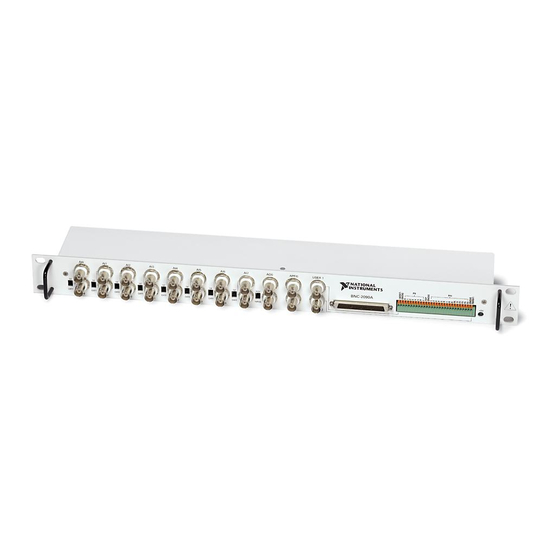
1 BNC Connectors
2 68-Position Connectors
The National Instruments BNC-2090A is a desktop or rack-mount analog
breakout accessory you can connect to E/M Series multifunction DAQ
devices. This quick start guide describes how to install and configure your
BNC-2090A accessory with a DAQ device.
Refer to the BNC-2090A User Manual for in-depth information about
accessory installation, cable connections, jumper settings, signals, and
signal conditioning, as well as accessory specifications.
Figure 1 shows the BNC-2090A front panel and enclosure back.
1
SE
SE
SE
SE
SE
SE
DIFF
DIFF
DIFF
DIFF
DIFF
DIFF
5
2
3 Spring Terminal Block
4 +5V LED
Figure 1. BNC-2090A Front Panel and Back of Enclosure
2
NATIONAL
INSTRUMENTS
BNC-2090A
RSE
NRSE
6
5 SE/DIFF Switches
6 RSE/NRSE Switch
3
4
Advertisement
Table of Contents

Subscribe to Our Youtube Channel
Related Manuals for National Instruments BNC-2090A


Summary of Contents for National Instruments BNC-2090A
- Page 1 BNC-2090A Rack-Mount Connector Accessory for E/M Series DAQ Devices The National Instruments BNC-2090A is a desktop or rack-mount analog breakout accessory you can connect to E/M Series multifunction DAQ devices. This quick start guide describes how to install and configure your BNC-2090A accessory with a DAQ device.
-
Page 2: Installing The Bnc-2090A
Installing the BNC-2090A To connect the BNC-2090A to your DAQ device, refer to Figure 2 as you complete the following steps. Consult your computer user manual or technical reference manual for specific instructions and warnings. Note If you have not already installed your DAQ device, refer to the DAQ Getting Started Guide for instructions. - Page 3 Two-connector M Series devices can be cabled to two BNC-2090A accessories with two cables. Note: Refer to the BNC-2090A User Manual for information about other E/M Series device connections. If the +5V LED does not light, check the cable connections.
-
Page 4: Connecting Differential Analog Input Signals
AI <0..7> BNC connector you use. Move the corresponding SE/DIFF switch to the DIFF position. On the BNC-2090A front panel, a line indicates which SE/DIFF switch corresponds to each AI <0..7> BNC connector. Configure your software to measure this channel differentially. -
Page 5: Connecting Single-Ended Analog Input Signals
Move the corresponding SE/DIFF switch to the SE position. On the BNC-2090A front panel, a line indicates which SE/DIFF switch corresponds to each AI <0..15> BNC connector. Move the RSE/NRSE switch to select how the ground signal is routed. -
Page 6: Connecting Digital Signals
Figure 5. Analog Output, APFI 0, and PFI 0 Connecting Digital Signals Use the BNC-2090A spring terminal block on the front panel to connect digital signals to your DAQ device. Refer to your DAQ device documentation for information on the use of these signals. -
Page 7: Using The User 1 And User 2 Bnc Connectors
The USER 1 and USER 2 BNC connectors allow you to use a BNC connector for a digital or timing I/O signal of your choice. The USER 1 and USER 2 BNC connectors are routed (internal to the BNC-2090A) to the USER1 and USER2 spring terminals, as shown in Figure 6. -
Page 8: Where To Go From Here
Instruments trademarks. Other product and company names mentioned herein are trademarks or trade names of their respective companies. For patents covering National Instruments products, refer to the appropriate location: Help»Patents in your software, the patents.txt file on your CD, or ni.com/patents.
Need help?
Do you have a question about the BNC-2090A and is the answer not in the manual?
Questions and answers