Table of Contents
Advertisement
Instruction Manual
D200108X012
Fisherr 546 Electro-Pneumatic Transducer
Contents
. . . . . . . . . . . . . . . . . . . . . . . . . . . . . . . . .
. . . . . . . . . . . . . . . . . . . . . . . . . . . . .
. . . . . . . . . . . . . . . . . . . . . . . . . . . . . . . . .
. . . . . . . . . . . . . . . . . . . . . . . . . . . . . . .
. . . . . . . . . . . . . . . . . . . . . . . . .
. . . . . . . . . . . . . . . . . . . . . . . . . . . . . . . . . .
. . . . . . . . . . . . . . . . . . . . . . . . . . . . . . . . . .
. . . . . . . . . . . . . . . . . . . . . . . . .
. . . . . . . . . . . . . . . . . . . . . . . . . . . . . . . .
. . . . . . . . . . . . . . . . . . . . . . . . . . . . . . . . .
. . . . . . . . . . . . . . . . . . . . . . . . . . .
. . . . . . . . . . . . . . . . . . . . . . . .
. . . . . . . . . . . . . . . . . . . . . . . .
. . . . . . . . . . . . . . . . . . . . . . . . . . . . . . . .
. . . . . . . . . . . . . . . . . . . . . . . . . . . .
. . . . . . . . . . . . . . . . . . . . . . . . . . . . . .
. . . . . . . . . . . . . . . . . . . . . . . . . . . . .
. . . . . . . . . . . . . . . . . . . . . . . . . . . . . . . . .
. . . . . . . . . . . . . . . . . . . . . . . . . . . . . . . . . . .
Introduction
Scope of Manual
This instruction manual provides installation, operation, maintenance, and parts ordering information for Fisher 546
transducers and the 82 relay. Refer to separate manuals for instructions covering equipment used with the transducer.
Do not install, operate or maintain a 546 transducer without being fully trained and qualified in valve, actuator and
accessory installation, operation and maintenance. To avoid personal injury or property damage it is important to
carefully read, understand, and follow all of the contents of this manual, including all safety cautions and warnings. If
you have any questions about these instructions, contact your Emerson Process Management sales office before
proceeding.
www.Fisher.com
. . . . . . . . . . . . . . . . . . . . . . . .
. . . . . . . . . . . . . . . . . . . . . .
. . . . . . . . . . . . . . . . . . . . . . . .
. . . . . . . . . . . . . . . . . . . . . .
. . . . . . . . . . . . . . . . . . . . .
. . . . . . . . . . . . .
. . . . . . . . . . . . . . . . . . . . . . .
. . . . . . . . . . . . . .
. . . . . .
. . . . . . . . . . . . . . . . . . . . . . .
. . . . . . . . . . . . . . . . . . . .
. . . . . . . . . . . . . . . . . . . .
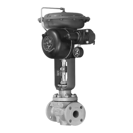
Figure 1. Fisher 546 Electro-Pneumatic Transducer
Mounted on a 657 Pneumatic Diaphragm Actuator
1
1
3
4
4
5
5
5
6
6
7
8
8
546
8
9
10
10
10
11
11
13
14
W2115
14
14
14
15
. . . . . . . . . . . . . . . . . . . . . . . . . . . . . . . . . . .
15
15
16
16
16
. . . . . . . . . . . . . . . . . . . . . . . . . . . . . . .
. . . . . . . . . . . . . . . . . . . . . . . . . . . . . . . . .
. . . . . . . . . . . . . . . . . . . . . . . . . . . . . . .
. . . . . . . . . . . . . . . . . . . . . . . . . . . . . .
. . . . . . . . . . . . . . . . . . . . . . . . . . . . .
. . . . . . . . . . . . . . . . . . . . .
546 Transducer
March 2015
FILTER
REGULATOR
16
17
17
17
18
20
22
Advertisement
Table of Contents

Related Manuals for Fisher 546


Summary of Contents for Fisher 546
-
Page 1: Table Of Contents
82 relay. Refer to separate manuals for instructions covering equipment used with the transducer. Do not install, operate or maintain a 546 transducer without being fully trained and qualified in valve, actuator and accessory installation, operation and maintenance. To avoid personal injury or property damage it is important to carefully read, understand, and follow all of the contents of this manual, including all safety cautions and warnings. - Page 2 Reference Accuracy: ±0.75% of output signal span explosion‐proof case and cover Independent Linearity: ±0.50% of output signal span The 546 can be ordered with or without a Fisher 67 Open Loop Gain: 26 filter regulator. A 51 mm (2 inch) circular supply Frequency Response: Gain is attenuated 3 dB at 20 Hz pressure gauge may be mounted on the regulator.
-
Page 3: Description
/hr—Normal cubic meters per hour (0_C and 1.01325 bar absolute). Scfh—Standard cubic feet per hour (60_F and 14.7 psia). 3. Performance values are obtained using a 546 transducer with a 4 to 20 mA DC input signal and a 0.2 to 1 bar (3 to 15 psig) or a 0.4 to 2 bar (6 to 30 psig) output signal. -
Page 4: Specifications
WARNING The 546 transducer does not meet third party approvals (CSA or FM) for use with natural gas as the supply medium. Use of natural gas as the supply medium can damage the instrument and result in personal injury or property damage from fire or explosion. -
Page 5: Installation
Mounting When a 546 transducer is ordered as part of a control valve assembly, the factory mounts the transducer on the actuator and connects the necessary tubing, then adjusts the transducer as specified on the order. Transducers also can be ordered separately for mounting on a control valve assembly already in service. The transducer may be ordered with or without mounting parts. -
Page 6: Diagnostic Connections
Instruction Manual 546 Transducer March 2015 D200108X012 If specified, the filter regulator is mounted on the transducer case. A pressure gauge on the regulator shows the supply pressure to the transducer. 1. Connect a supply pressure source to the 1/4 NPT IN connection on the filter regulator (if furnished) or to the 1/4 NPT SUPPLY connection on the transducer case (if a regulator is not furnished). -
Page 7: Operating Information
Instruction Manual 546 Transducer D200108X012 March 2015 For explosion‐proof applications, install rigid metal conduit and a conduit seal no more than 457 mm (18 inches) from the transducer. Personal injury or property damage may result from explosion if the seal is not installed. -
Page 8: Adjustments
Instruction Manual 546 Transducer March 2015 D200108X012 If the transducer is installed in an application where explosion‐proof classification is required, perform the following steps (prior to removal of the transducer cover) when any procedure in this section requires removal of the cover: D Disconnect the electrical signal from the transducer. -
Page 9: Calibration Procedure
Note The following calibration procedure is for a 546 transducer with a 4 to 20 mA DC input signal range and a 0.2 to 1.0 bar (3 to 15 psig) output range. Calibrate transducers with other inputs and outputs in a similar manner. -
Page 10: Recalibration
Reversing the Action Reversing the action of a 546 transducer requires no special parts. The direction of armature rotation is dependent upon the direction of the current flow. Therefore, simply reverse the input current leads to the transducer to obtain... -
Page 11: Split Range Operation
Split Range Operation 546 transducers are suitable for two‐way split range operation. In a two‐way split the milliampere (mA) or voltage output signal of a single control device is split between two transducers electrically connected in series. Although each transducer receives the full signal, it is calibrated to provide a full output pressure range of 0.2 to 1.0 bar (3 to 15 psig) - Page 12 Instruction Manual 546 Transducer March 2015 D200108X012 Figure 7 shows output‐time relationship curves for loading and exhausting an actuator. Exhausting times are nominally 25 percent of the loading times. Reverse‐acting transducers operate in a similar manner except that when the DC input signal increases, the output pressure from the relay decreases.
-
Page 13: Maintenance
Instruction Manual 546 Transducer D200108X012 March 2015 Maintenance Maintenance of the transducer consists of relay repair or replacement, and replacement of the feedback bellows. WARNING The following maintenance procedures require that the transducer be taken out of service. This requires that certain precautions be taken to avoid personal injury or equipment damage caused by sudden release of pressure. -
Page 14: Relay Removal And Replacement
Instruction Manual 546 Transducer March 2015 D200108X012 CAUTION Never disassemble the torque motor assembly because the magnetism in the torque motor magnets will decrease permanently. Shaded key numbers indicate parts that should not be disassembled from the torque motor (see figure 9). If troubleshooting or alignment attempts indicate either a faulty torque motor or the necessity of disassembling the torque motor consult your Emerson Process Management sales office. -
Page 15: Pneumatic
Instruction Manual 546 Transducer D200108X012 March 2015 4. Check the terminal lugs for proper connections. If reverse action of the transducer is observed, simply reverse the input leads as indicated in the Reversing the Action procedures in the Operating Information section. -
Page 16: Torque Motor Frame
Use only genuine Fisher replacement parts. Components that are not supplied by Emerson Process Management should not, under any circumstances, be used in any Fisher instrument. The use of components not manufactured by Emerson Process Management may void your warranty, might adversely affect the performance of the instrument, and could result... -
Page 17: Parts List
82 Relay Replacement Assembly Assembly includes 6* O‐Ring, nitrile 1D444806992 two mounting screws (Key 68) 10A8593X072 8* Pressure Gauge 546 Transducers (figure 8) Triple scale 0-30 psig/0-.2 MPa/0-2 bar 11B8582X012 0-60 psig/0-.4 MPa/0-4 bar 11B8582X022 Dual scale Note 0-30 psig/0-2 Kg/cm 11B8582X042 Part numbers are shown for recommended spares only. -
Page 18: Torque Motor
Instruction Manual 546 Transducer March 2015 D200108X012 Figure 9. Torque Motor Assembly APPLY LUBRICANT/SEALANT NOTES: 1. SHADED KEY NUMBERS INDICATE PARTS THAT SHOULD NOT BE DISASSEMBLED FROM TORQUE MOTOR. 2. KEY NUMBERS 22 AND 103 ARE NOT SHOWN. 30A8594‐K B1767‐3... - Page 19 Bottom Pole Piece Plate 52 Travel Stop Note 53 Terminal Mounting Bracket Ass'y The 546 relay is not repairable. If the relay is defective, order the 82 55 Span Adjustment Ass'y Relay Replacement Assembly (refer to Parts Kits). 56 Bellows Screw, brass *Recommended spare parts 1.
-
Page 20: Mounting Parts
Instruction Manual 546 Transducer March 2015 D200108X012 Mounting Parts (figures 11 & 12) Description 82 Cap Screw, steel pl Yoke mounting (4 req'd) 480 all sizes 513 all sizes 656 size 40 thru 60 Note 657 & 667 size 30 thru 80 1051 size 40 &... - Page 21 Instruction Manual 546 Transducer D200108X012 March 2015 Figure 11. Typical Actuator Mounting Figure 12. Typical Casing Mounting TRANSDUCER 1051/52 SIZE 33 ACTUATOR 42B0737‐A A5426‐1 / IL TRANSDUCER Description 585 SIZE 25 AND 50 ACTUATORS 97 U‐Bolt, steel pl (2 req'd) 48A9176‐B...
-
Page 22: Diagnostic Connections
Instruction Manual 546 Transducer March 2015 D200108X012 Diagnostic Connections FlowScannert diagnostic system hook‐up Includes pipe tee, pipe nipple, pipe bushings, connector body, and body protector. See figure 3 for part identification. Note Part numbers are shown for recommended spares only. For part numbers not shown, contact your Emerson Process Management sales office. - Page 23 Instruction Manual 546 Transducer D200108X012 March 2015...
- Page 24 Responsibility for proper selection, use, and maintenance of any product remains solely with the purchaser and end user. Fisher and FlowScanner are marks owned by one of the companies in the Emerson Process Management business unit of Emerson Electric Co. Emerson Process Management, Emerson, and the Emerson logo are trademarks and service marks of Emerson Electric Co.
Need help?
Do you have a question about the 546 and is the answer not in the manual?
Questions and answers