Table of Contents
Advertisement
Instruction Manual
D103198X012
Fisherr i2P-100 Electro-Pneumatic Transducer
Contents
. . . . . . . . . . . . . . . . . . . . . . . . . . . . . . . . .
. . . . . . . . . . . . . . . . . . . . . . . . . . . . .
. . . . . . . . . . . . . . . . . . . . . . . . . . . . . . . . .
. . . . . . . . . . . . . . . . . . . . . . . . . . . . . . .
. . . . . . . . . . . . . . . . . . . . . . . . .
. . . . . . . . . . . . . . . . . . . . . . . . . . . . . . . . . .
. . . . . . . . . . . . . . . . . . . . . . . . . . . . . . . . . . . .
FM
. . . . . . . . . . . . . . . . . . . . . . . . . . . . . . . . . . . . .
. . . . . . . . . . . . . . . . . . . . . . . . . . . . . . . . . . .
. . . . . . . . . . . . . . . . . . . . . . . . . . . . . . . . . .
. . . . . . . . . . . . . . . . . . . . . . . . . . . . . . . . .
. . . . . . . . . . . . . . . . . . . . . . . . . . . . . . . . . .
. . . . . . . . . . . . . . . . . . . . . . . .
. . . . . . . . . . . . . . . . . . . . . . . . . . . . . . . .
. . . . . . . . . . . . . . . . . . . . . . . .
. . . . . . . . . . . . . . . . . . . . . . . . . . . . . . . .
. . . . . . . . . . . . . . . . . . . . . . . . . . . .
. . . . . . . . . . . . . . . . . . . . . . . . . .
Introduction
Scope of Manual
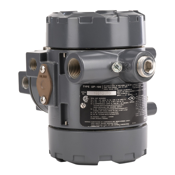
This instruction manual provides installation, operation, maintenance, and parts ordering information for the Fisher
i2P-100 transducer (see figure 1).
Refer to separate manuals for instructions covering equipment used with the transducer.
Do not install, operate, or maintain an i2P-100 electro-pneumatic transducer without being fully trained and qualified
in valve, actuator, and accessory installation, operation and maintenance. To avoid personal injury or property
damage it is important to carefully read, understand, and follow all of the contents of this manual, including all safety
cautions and warnings. If you have any questions about these instructions, contact your Emerson Process
Management sales office.
www.Fisher.com
. . . . . . . . . . . . . . . . . . . . .
. . . . . . . . . . . . . . . . . . . . .
. . . . . . . . . . . .
. . . . . . . . . . . . . . . . . .
. . . . . . . . . . . . . . . . . . . . . . .
. . . . . . . . . . . . . . . . . . . . .
. . . . . . . . . . . . . . . . . . . .
. . . . . . . . . . . . . .
. . . . . . . . . . . . . .
Figure 1. Fisher i2P-100 Electro-Pneumatic
Transducer
1
1
2
2
2
5
7
7
8
8
10
11
INTEGRAL
11
PNEUMATIC
12
RELAY
13
14
W8710
14
15
15
16
16
17
. . . . . . . . . . . . . . . . . . . . . . . . . . . . . . . . . . .
18
19
20
20
21
i2P-100 Transducer
. . . . . . . . . . . . . . . . . . . . . . . . . . . . . . .
. . . . . . . . . . . . . . . . .
. . . . . . . . . . . . . . . . . . . . . . . .
. . . . . . . . . . . . . . . .
. . . . . . . . . . . . . . . . . . . . . . . . .
. . . . . . . . . . . . .
July 2014
REPLACEABLE
FILTER WITH
REMOVABLE
ORIFICE
VENT
22
23
26
26
26
27
27
Advertisement
Table of Contents

Related Manuals for Fisher i2P-100


Summary of Contents for Fisher i2P-100
-
Page 1: Table Of Contents
Refer to separate manuals for instructions covering equipment used with the transducer. Do not install, operate, or maintain an i2P-100 electro‐pneumatic transducer without being fully trained and qualified in valve, actuator, and accessory installation, operation and maintenance. To avoid personal injury or property damage it is important to carefully read, understand, and follow all of the contents of this manual, including all safety cautions and warnings. -
Page 2: Description
Instruction Manual i2P-100 Transducer July 2014 D103198X012 CAUTION Dropping or rough handling of the transducer can cause damage to the converter module resulting in a shifted output or a minimum output. Description The transducer receives a 4‐20 mA DC input signal and transmits a proportional user field‐configurable pneumatic output pressure to a final control element. - Page 3 Instruction Manual i2P-100 Transducer D103198X012 July 2014 Table 1. Specifications Input Signal Performance Reference Accuracy: ±1.0% of full scale output span; Available as standard with 4‐20 mA. includes combined effects of hysteresis, linearity, and User configurable by dip switch for split ranging, see deadband table below.
-
Page 4: Management Sales Office
Declaration of SEP Contact your Emerson Process Management sales office for classification/certification specific Fisher Controls International LLC declares this information product to be in compliance with Article 3 paragraph 3 of the Pressure Equipment Directive (PED) 97 / 23 / Connections EC. -
Page 5: Installation
Scfh - Standard cubic feet per hour (60F and 14.7psig). 2. Natural gas steady state flow based on natural gas specific gravity of 0.6. Flow decreases as specific gravity increases. Figure 2. Output‐Time Relationships for Fisher i2P‐100 Transducer LOADING EXHAUSTING... - Page 6 Instruction Manual i2P-100 Transducer July 2014 D103198X012 WARNING To avoid personal injury or property damage from the sudden release of pressure, air, or natural gas: D Always wear protective clothing, gloves, and eyewear when performing any installation operations. D If installing into an existing application, also refer to the WARNING at the beginning of the Maintenance section of this instruction manual.
-
Page 7: Hazardous Area Classifications And Special Instructions For "Safe Use" And Installation In Hazardous Locations
Instruction Manual i2P-100 Transducer D103198X012 July 2014 Hazardous Area Classifications and Special Instructions for “Safe Use” and Installation in Hazardous Locations Certain nameplates may carry more than one approval, and each approval may have unique installation/wiring requirements and/or conditions of “safe use”. These special instructions for “safe use” are in addition to, and may override, the standard installation procedures. -
Page 8: Atex
Instruction Manual i2P-100 Transducer July 2014 D103198X012 Special Conditions of Use Intrinsically Safe, Explosion-proof, Type n, Non‐incendive, Dust‐Ignition proof 1. When product is used with natural gas as the pneumatic medium, the maximum working pressure of the natural gas supply is limited to 50 psi. - Page 9 Instruction Manual i2P-100 Transducer D103198X012 July 2014 Special Conditions for Safe Use Intrinsically Safe 1. Before putting in service, the user shall permanently cross out the areas on the nameplate with the types of protection that are not applicable (Ex ia IIC T3... T5, KEMA 05ATEX1109 X or Ex nA II T5/T6, KEMA 05ATEX1119) or mark the selected type of protection.
-
Page 10: Iecex
Instruction Manual i2P-100 Transducer July 2014 D103198X012 Table 7. Hazardous Area Classifications—ATEX Certificate Certification Obtained Entity Rating Temperature Code Enclosure Rating Intrinsically Safe Ui = 30 VDC II 1 GD T3 (Tamb ≤ 85°C) Ii = 100 mA T4 (Tamb ≤ 81°C) IP66* Pi = 1.0 W... -
Page 11: Mounting
See figures 3 and 4 for typical mounting configurations. Figure 3. Fisher i2P‐100 Electro‐Pneumatic Figure 4. Fisher i2P‐100 Electro‐Pneumatic Transducer Mounted on a Size 30 667 Sliding‐Stem... -
Page 12: Supply Pressure Requirements
Supply pressure must be clean, dry air or noncorrosive gas. Use a Fisher 67CFR filter regulator with standard 5 micrometer filter, or equivalent, to filter and regulate supply air. The filter regulator can be mounted on a bracket with the transducer as shown in figure 6 or mounted on the actuator mounting boss. -
Page 13: Diagnostic Connections
Instruction Manual i2P-100 Transducer D103198X012 July 2014 Figure 6. Typical Fisher i2P‐100 Mounting With 67CFR Filter Regulator i2P‐100 TRANSDUCER MOUNTING BRACKET REGULATOR PIPE CHAMFER 45_ to 27/64 DIA NIPPLE 1/4‐18 NPT EXTERNAL 2.5 INCH Diagnostic Connections To support diagnostic testing of valve/actuator/positioner packages, special connectors and hardware are available. -
Page 14: Vent
Instruction Manual i2P-100 Transducer July 2014 D103198X012 Note If the i2P‐100 transducer is used in a valve assembly with a positioner, no hook‐up for diagnostic testing is required for the i2P‐100. The hook‐up for diagnostic testing should be installed at the positioner. -
Page 15: Operating Information
Instruction Manual i2P-100 Transducer D103198X012 July 2014 WARNING Select wiring and/or cable glands that are rated for the environment of use (such as hazardous location, ingress protection, and temperature). Failure to use properly rated wiring and/or cable glands can result in personal injury or property damage from fire or explosion. -
Page 16: Equipment Required
Instruction Manual i2P-100 Transducer July 2014 D103198X012 For intrinsically safe areas, current monitoring during operation must be with a meter approved for use in hazardous areas. Equipment Required Choose a current or voltage source that is capable, without switching ranges, of driving the transducer through its entire input range. -
Page 17: Principle Of Operation
Instruction Manual i2P-100 Transducer D103198X012 July 2014 1. Remove electronics module cover (cover adjacent to conduit entry, see figure 3 and 4). CAUTION Do not attempt to remove either of the housing caps if the locking set screws (key 8) are engaged. Removing housing caps without disengaging the set screws can cause damage to the housing caps. -
Page 18: Maintenance
Instruction Manual i2P-100 Transducer July 2014 D103198X012 Figure 11. Fisher i2P‐100 Transducer Schematic FIELD TERMINATOR AND ELECTRONICS CIRCUIT CURRENT‐TO‐PRESSURE CONVERTER ASSEMBLY COIL MAGNET ZERO BEAM SPAN CIRCUIT FLAPPER CURRENT NOZZLE INPUT SIGNAL PNEUMATIC RELAY DIAPHRAGM EXHAUST RESTRICTION VALVE PLUG DIAPHRAGM... -
Page 19: Troubleshooting
Instruction Manual i2P-100 Transducer D103198X012 July 2014 D Remove electrical power before removing either housing cap. Personal injury or property damage from fire or explosion may result if power is not disconnected before removing either cap. D Remove electrical power before disconnecting any of the pneumatic connections or removing the external removable filter/restriction. -
Page 20: Converter Module Replacement
Instruction Manual i2P-100 Transducer July 2014 D103198X012 3. If a filter/regulator is used, ensure that it is working correctly. If not, ensure the dripwell is not plugged because of excessive moisture accumulation. If necessary, drain off any moisture, and clean or replace the filter element. -
Page 21: Relay Maintenance
Instruction Manual i2P-100 Transducer D103198X012 July 2014 3. Electrically calibrate the unit using the procedure in the Calibration section of this manual. 4. Replace the housing cap (key 2), making sure to re‐tighten the set screw (key 8). Relay Maintenance Refer to figures 12 and 14 for key number locations. -
Page 22: Parts Ordering
Use only genuine Fisher replacement parts. Components that are not supplied by Emerson Process Management should not, under any circumstances, be used in any Fisher instrument. Use of components not supplied by Emerson Process Management may void your warranty, might adversely affect the performance of the instrument, and could cause personal... -
Page 23: Parts List
Instruction Manual i2P-100 Transducer D103198X012 July 2014 Figure 13. Fisher i2P‐100 Transducer Assembly NOTE: APPLY LUBRICANT/SEALANT/ADHESIVE 30C2230‐C Parts Kits Housing Description Part Number Description Part Number Housing, Aluminum Cover (2 req'd) Repair Kit for i2P‐100 electro‐pneumatic transducer Configuration Label Contains O‐rings (key 4, 9, 12, and 55) and O‐Ring... - Page 24 Instruction Manual i2P-100 Transducer D103198X012 July 2014 Figure 14. Fisher i2P‐100 Relay Assembly TABS ON BODY BLOCK AND RELAY BODY MUST ALIGN WITH TAB ON THE TRANSDUCER HOUSING ASSEMBLY NOTE: APPLY LUBRICANT/SEALANT/ADHESIVE 30C2258‐B Description Part Number Description PWB/Cup Assembly Diagnostic Connections...
- Page 25 Instruction Manual i2P-100 Transducer D103198X012 July 2014 Description Description Mounting Parts Casing Mounting 657 and 667 size 30, 34, 40, 45, 50 and 60 Mounting Bracket, steel Note Washer, steel pl (2 req'd) Contact your Emerson Process Management sales office for i2P‐100 Cap Screw, steel pl (2 req'd) mounting FS number.
-
Page 26: Loop Schematics/Nameplates
Instruction Manual i2P-100 Transducer July 2014 D103198X012 Loop Schematics/Nameplates Figure 15. CSA Loop Schematic GE07471_B Figure 16. Typical CSA/FM Approval Nameplate... -
Page 27: Fm Loop Schematic
Instruction Manual i2P-100 Transducer D103198X012 July 2014 Figure 17. FM Loop Schematic GE07470_B Figure 18. Typical ATEX/IECEx Approval Nameplate ATEX TYPE n ATEX INTRINSICALLY SAFE ATEX FLAMEPROOF IECEx APPROVAL INFORMATION... - Page 28 Responsibility for proper selection, use, and maintenance of any product remains solely with the purchaser and end user. Fisher and FlowScanner are marks owned by one of the companies in the Emerson Process Management business unit of Emerson Electric Co. Emerson Process Management, Emerson, and the Emerson logo are trademarks and service marks of Emerson Electric Co.
Need help?
Do you have a question about the i2P-100 and is the answer not in the manual?
Questions and answers