Table of Contents
Advertisement
Advertisement
Table of Contents

Related Manuals for Unipower HPL110/220

Summary of Contents for Unipower HPL110/220
-
Page 1: Installation And Operation
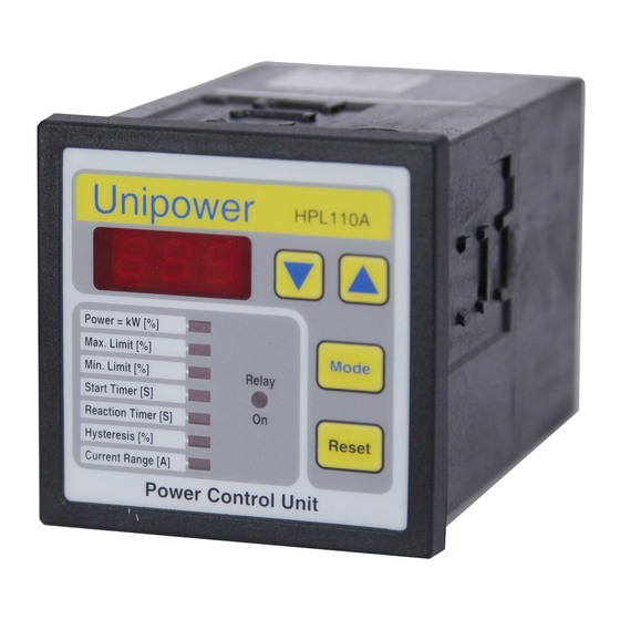
Unipower ® HPL1 1 0A D i g i t a l P o w e r M o n i t o r Installation and Operation True Motor Power Monitor with... • High Trip Alarm • Low Trip Alarm •... -
Page 2: Table Of Contents
Contents System Overview Functional Description Typical Applications System Configuration Electrical Installation: 3-Phase Power Connection 1-Phase Power Connection Alarm Relay States Alarm Integration Reset Function Specifications: Technical Specifications DIP Switches Mechanical Installation HPL110A Current Transformer Programming Troubleshooting 10 Set-Up Log Sheet WARNING: Dangerous voltages are present in motor control panels;... -
Page 3: System Overview
System Overview The Unipower HPL110A advanced digital power monitor is a member of the Unipower family of “Intelligent Power- Control Units” designed for protection and control of motor driven mechanical systems. The HPL110A measures true power consumption of 3-phase AC motors... -
Page 4: Functional Description
Functional Description The Unipower HPL110A may be used either for monitoring applications - to protect process equipment - or for control applications - to control secondary process functions. Monitoring Example for Machinery Protection A typical Power vs. Time graph for the HPL110A is shown in Figure 2.1 with the Y-axis showing power P in units of %kW and the X-axis showing time. - Page 5 The HPL110A functions in these examples are as follows: Power %kW: The display shows true power in units of % of full scale for the HPL110A as installed. Ts - Start Delay Timer: Ts is used to delay the start of active monitoring until after the start surge is completed.
- Page 6 Control Example While monitoring for machinery protection is the primary application for the HPL110A, it is also suitable for simple two-point control regulation applications by using the Hysteresis function included in the unit. A possible control example might be where the HPL110A is monitoring the power consumed to mix a slurry and the relay output is used to add liquid if the slurry becomes too viscous.
-
Page 7: Typical Applications
Typical Applications Seal-less Centrifugal Pumps These “positive pressure” pumps have a power curve which is proportional to flow rate. Power monitoring using the HPL110A, therefore, is very effective for ensuring the pump is running within the design minimum and maximum flow limits. This is particularly true of seal-less pumps where dry-running can quickly result in damage or failure of the pump and containment system. -
Page 8: System Configuration
System Configuration The Unipower HPL110A measures voltage in all three legs of the 3-phase supply (or one leg and neutral for single phase versions) and current in one leg. The HPL110A has an internal current transformer with a measurement range of 8 Amps. - Page 9 Full Load Current Ratio Primary HPL110 Range Effective Range Amps Transformer Primary : Secondary Turns Setting Amps Internal 1 : 1 Internal 1 : 1 Internal 1 : 1 Internal 1 : 1 HF3A,050/5 50 : 5 HF3A,050/5 50 : 5 HF3A,050/5 50 : 5 HF3A,050/5...
-
Page 10: Electrical Installation
Installation - Electrical 5.1 3-PHASE HOOK-UP The HPL110A should be connected directly in front of the motor starter unit and downstream of the motor fuses and/or isolation breaker as shown in Figure 5.1. An external current transformer with a secondary rating of 1 or 5 amps must be used if the rated full load motor current is in excess of 8 amps. -
Page 11: Alarm Relay States
5.2 SINGLE PHASE HOOK-UP Figure 5.2 shows correct connection for single phase mains units. The single phase version of the HPL110A requires a 24V secondary isolation transformer (supplied) with the L2 - Neutral side of the secondary grounded. HPL110A Motor Fuses 24V Secondary Isolation... -
Page 12: Alarm Integration
5.4 ALARM INTEGRATION In order for the HPL110A to stop the motor in the event of an alarm, the alarm relay (terminals 9, 10 and 11) must be integrated into the motor starter circuit such that it duplicates the effect of activating the STOP button. One possibility is shown in Figure 5.4 where the NC relay contacts (terminals 9 and 10) are connected in series with the STOP button. -
Page 13: Specifications
Specifications 6.1. TECHNICAL SPECIFICATIONS Electrical Mechanical Voltage Range: See unit for range Housing: Noryl Standard ranges— Mounting: Panel mounting for 3 x 220, x 380, x 460, x 575 2.64” x 2.64” cut-out (67 x 67 mm) Also available— Min. mounting depth 5” (125 mm) 1 x 24V for 110/220V single phase Protection Class: IP54 Current Range:... -
Page 14: Mechanical Installation
Installation - Mechanical HPL110A Module The HPL110A unit is designed to be mounted through a panel of an enclosure with the face exposed and the body protected within. A square cut-out is required of 2.64" x 2.64" (67 x 67 mm), the HPL110A is installed through the cut-out and retained with fittings supplied. -
Page 15: Current Transformer
Current Transformers The optional HF3Axxx/x series current transformers may be mounted either directly to standard 35mm DIN rail, as shown on Page 9, using accessory 741B0231 - not included - or screwed directly to a panel using two M5 or #10 cap screws with accessory 741B0230/6 - not included - as shown in Fig. -
Page 16: Programming
Programming The Modes and Programming ranges for the HPL110A are given in the Function Table below: Mode Function Variable Display Default Power=kW(%) kW display Min.Peak Max.Peak kW (%) Max. Limit Max.kW Limit 5-100%/off Decrease Increase Off/Max.Limit (%) Min.Limit (%) Min.kW Limit Off/5-100% Decrease Increase... - Page 17 Use the values noted to set the remaining program parameters as described below. 8.3 TS: START TIMER The Ts Start Delay Timer is used to inhibit monitoring during the motor start-up surge. To determine the appropriate value for Ts, start the motor and observe how long - seconds - it takes for the HPL110A kW[%] display value to stabilize.
-
Page 18: Dip Switch Functions
8.7 RESPONSE TEST A system response test should now be carried out to ensure that the HPL110A correctly stops the motor in the event of an alarm. To do this, run the system under normal conditions - no alarm should occur - and then depress the MODE key to select Max. Alarm [%] mode. -
Page 19: Troubleshooting
Trouble Shooting Symptom Suggestion No Display HPL110A is not getting power, check mains electrical connection Display stays at “000” HPL110A is not receiving a current signal, check that with motor running full L3 current is flowing into Terminal 7 and back out of Terminal 8 or from Secondary Terminals—S1 and S2—of current transformer, if used. -
Page 20: Set-Up Log Sheet
Full Load Power Rated Full Load Current Rated Mains Voltage Mains Frequency 60 Hz 50 Hz Phase 3-Phase 1-Phase Rated Efficiency ® Unipower HPL110A Model HPL110A/xxx Current Transformer None 50/5 75/5 100/5 150/5 Turns through CT Program Current Range (A) Start Time (S) Max.
Need help?
Do you have a question about the HPL110/220 and is the answer not in the manual?
Questions and answers