Table of Contents
Advertisement
Quick Links
LOVATO ELECTRIC S.P.A.
24020 GORLE (BERGAMO) ITALIA
VIA DON E. MAZZA, 12
TEL. 035 4282111
FAX (Nazionale): 035 4282200
FAX (International): +39 035 4282400
L
E
E-mail info@
ovato
lectric.com
L
E
Web
www.
ovato
lectric.com
WARNING!
– Carefully read the manual before the installation or use.
– This equipment is to be installed by qualified personnel, complying to current standards, to avoid
damages or safety hazards.
– Disconnect the power supply before any connection or disconnection is done through the charger
terminal block.
– The manufacturer cannot be held responsible for electrical safety in case of improper use of the
equipment.
– Products illustrated herein are subject to alteration and changes without prior notice. The technical
data and description in this documentation are subject to alterations and changes at any time and
have no contractual value.
– A circuit breaker easy accessible must be included outside of the device.
– The device is exclusively intended for installation in areas accessible only to service personnel as
defined by chapter 1.2.13.5 of IEC/EN 60950-1.
– Clean the instrument with a soft dry cloth; do not use abrasives, liquid detergents or solvents.
IMPORTANT
– Do not use the battery charger in proximity of explosive gases and/or other inflammable material.
– Arrange for adequate air flow of the battery room during recharging.
– Should the battery charger be disconnected from the power supply for a long period of time, it is
recommended to disconnect the batteries from the battery charger. Connection for long periods of
inactivity may discharge the batteries.
INTRODUCTION
The "BCG" device is a battery charger working with constant voltage and constant current charge cycle
suitable for lead-acid batteries. Different versions are available: BCG 0612 (12V – 6A), BCG0524 (24V –
5A), BCG 01212 (12V – 12A) and BCG1024 (24V – 10A). The maximum current is then adjustable in a
range between 20% and 100% of full scale. The charging voltage is selectable between two levels and a
boost voltage can be applied as well.
The protection trips are indicated by LEDs and output contact.
The switching technology which BCGs are based on lets high efficiency and at the same time a wide
range of power supply.
Based, din rail or vertical mounting with the appropriate accessory (only BCG0612 and BCG0524
versions) can be choosen.
DESCRIPTION
– Switching technology
– Reduced weight and dimensions
– Wide range power supply (110...240VAC)
– High efficiency
– "Constant current" – "Constant voltage" charging cycle (DIN41773)
– 2 charging voltage levels selectable through dip switches (2.25V and 2.3V per battery element)
– Trimmable charging current (from 20% to 100% of rated value)
– External BOOST command to deeply charge the battery
– "Hiccup" function to charge the battery in case of battery voltage level lower than 50% of rated one
– "Low battery voltage", "short circuit" and "reverse battery" alarms.
– 4 signalling LEDs
– 1 relay output to remote the battery status (with changeover contact)
– Operating temperature -30...+55°C (70°C with derating)
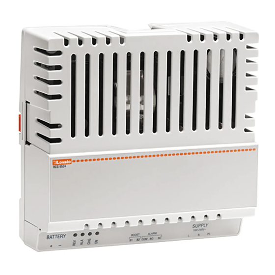
SIGNALLING DESCRIPTION
LED "ON" (Power ON) indicates that the battery charge is power supplied.
LED "CHG" (CHARGE) means the charging current is higher than 30% of the set one.
LED "ALA" (ALARM) warns about an alarm condition.
LED "REV" (REVERSE) indicates that the battery connection is inverted.
ALARM RELAY
The battery charger is equipped with a normally powered changeover relay output. In case of alarms
("ALARM" or "REVERSE" LED on) the relay output is not powered.
CONNECTIONS
Keep the distance between the battery charger and the battery as short as possible; consider the use of
cables of the right size to avoid voltage drops which can cause an incorrect battery charging.
Connect all those devices which need the battery voltage directly to the battery poles and not to the
battery charger terminals.
Connect the battery poles to the device battery terminals before powering on the battery charger and
control the battery connection through REV LED it must be off.
Install a fuse at the battery charger output terminals (See technical characteristics).
GB
AUTOMATIC BATTERY CHARGER
Instruction manual
PL
AUTOMATYCZNE ŁADOWARKI AKUMULATORÓW
Instrukcja obsługi
BCG0612 - BCG0524
BCG1212 - BCG1024
– Należy dokładnie przeczytać instrukcje przed instalacją lub użytkowaniem.
UWAGA!
– By uniknąć zagrożenia życia oraz mienia urządzenia powinny być instalowane przez wykwalifikowany
personel w zgodzie z wymogami standardów elektrycznych.
– Należy odłączyć zasilanie przed wykonywaniem czynności podłączenia/odłączenia przewodów od zacisków
ładowarki.
– Producent nie ponosi odpowiedzialności za bezpieczeństwo elektryczne w przypadku niewłaściwego
użycia urządzeń.
– Produkty opisane w tym dokumencie moga ulec zmianie lub ulepszeniu w dowolnym momencie.
Opisy i dane nie mają wartości kontraktowej.
– W układzie należy zastosować wyłącznik nadprądowy, który należy zamontować w pobliżu urządzenia
i z łatwym dostępem dla operatora, zgodny z normą: 1.2.13.5 della IEC/EN 60950-1.
– Urządzenie należy czyścić delikatną szmatką bez użycia środków ścierających, płynnych
detergentów lub rozpuszczalników.
WAŻNE
– Nie można stosować ładowarki w pobliżu wybuchowych gazów i/lub innych łatwopalnych materiałów.
– Należy zapewnić właściwy przepływ powietrza w pomieszczeniu gdzie znajduje się ładowarka (podczas
ładowania).
– Jeśłi ładowarka będzie odłączona od zasilania przez dłuższy czas to zaleca się odłączenie akumulatora od
ładowarki. Niezasilana ładowarka może rozładować akumulator.
WPROWADZENIE
Urządzenia serii "BCG" pracują w cyklu ładowania stałą wartością napięcia i stałą wartością prądu akumulatorów
kwasowo-ołowiowych. Dostępne wersje: BCG 0612 (12V – 6A), BCG0524 (24V – 5A), BCG 01212 (12V – 12A)
oraz BCG1024 (24V – 10A). Prąd maksymalny ładowania może być regulowany w zakresie od 20% do 100%
pełnej skali. Napięcie ładowania może zostać wybrane z dwóch dostępnych wartości; ładowarka ma funkcję
podniesienia napięcia. Zadziałanie ochrony sygnalizowane jest wskaźnikami LEd i wyjściem przekaźnikowym.
Technologia impulsowa gwarantuje wysoką sprawność pracy ładowarek BCG oraz szeroki zakres napięcia
zasilania.
Ładowarki "BCG" moga być montowane na szynie DIN lub pionowo przy użyciu specjalnych akcesorió (tylko BCG
0612 i BCG0524).
OPIS
– Technologia impulsowa
– Zredukowane wymiary oraz masa
– Szeroki zakres napięcia wejściowego (110...240VAC)
– Wysoka sprawność
– Cykl ładowania: "stała wartość prądu" – "stała wartość napięcia" (DIN41773)
– 2 wartości napięcia ładowania, wybierane przełącznikiem (2,25V i 2,3V na element akumulatora)
– Prąd ładowania w zakresie od 20% do 100%
– Zewnętrzna komenda „wzmocnienia" ładowania akumulatora
– Funkcja"Hicc-up" do ładowania akum.w przypadku, gdy jego napięcie jest niższe niż 50% wart. znamionowej
– Alarmy: "Niskie napięcie akumulatora", "Zwarcie" i "Odwrotna polaryzacja akumulatora".
– 4 wskaźniki LED
– 1 wyjście przekaźnikowe do zdalnej sygnalizacji statusu ładowarki (zestyk przełączny)
– Temperatura pracy: -30...+55°C (70°C z obniżeniem wartości znamionowych)
OPIS SYGNALIZACJI
LED "ON" (Power ON) wskazuje, iz ładowarka jest zasilona.
LED "CHG" (CHARGE) wskazuje, iż prąd ładowania jest wyższy niż 30% ustawionej wartości.
LED "ALA" (ALARM) wskazuje warunki alarmowe.
LED "REV" (REVERSE) wskazuje, iż podłączenie akumulatora zostało wykonane odwrotnie niż powinno.
PRZEKAŹNIK ALARMOWY
Ładowarka wyposażona jest w wyjście alarmowe (przekaźnik normalnie wzbudzony). W przypadku alarmów (LED
"ALARM" lub "REVERSE" włączony) lub przy braku napięcia sieci przekaźnik wyjściowy będzie odwzbudzony.
PODŁĄCZENIE
Odległość między ładowarką a akumulatorem powinna być jak najmniejsza; należy używać właściwych
przewodów (przekrój), które uwzględniają spadek napięcia powstający przy niewłaściwym ładowaniu akumulatora.
Na początku należy podłączyć wszystkie urządzenia, które będą zasilane z baterii, do zacisków akumulatora,
nie podłączając nic do zacisków ładowarki.
Następnie należy podłączyć zaciski akumulatora do ładowarki, bez podłączenia zasilania do wejścia ładowarki,
i sprawdzić polaryzację (dioda LED REV wyłączona).
Należy zainstalowac bezpiecznik na wyjściu ładowarki (zobacz Dane techniczne).
1
Advertisement
Table of Contents

Related Manuals for LOVATO ELECTRIC BCG0612


Summary of Contents for LOVATO ELECTRIC BCG0612
-
Page 1: Instruction Manual
The switching technology which BCGs are based on lets high efficiency and at the same time a wide 0612 i BCG0524). range of power supply. Based, din rail or vertical mounting with the appropriate accessory (only BCG0612 and BCG0524 versions) can be choosen. OPIS –... - Page 2 Alarms RELAY Alarmy PRZEKAZ. ZIELONY CZERWON. CZERWON. ZÓŁTY Correct output voltage Energised Napięcie wyjściowe OK Wzbudzony ON ( ) ON ( ) Charging Energised Ładowanie Wzbudzony ON (2) ON (2) Niskie napięcie akumulatora Wzbudzony Low battery voltage Energised Odwrotna polaryzacja Odwzbudzony Reverse polarity De-energised...
- Page 3 CURRENT LIMIT ATTENTION: UWAGA: Mount the terminal cover after connection. Należy zamontowac pokrywę ochronną zaciskó po okablowaniu. BCG0612 - BCG0524 MECHANICAL DIMENSIONS [mm] WYMIARY MECHANICZNE [mm] BCG0612 - BCG0524 Standard (horizontal) mounting Montaż standardowy (poziomo) 63.2 Electrical data label position...
- Page 4 TECHNICAL CHARACTERISTICS Supply Model BCG0612 BCG0524 BCG1212 BCG1024 Rated voltage Us 110 - 240V Operating voltage range 100 - 264V Frequency 45 - 66Hz Maximum current consumption at rated voltage 240V 0.96A 110V 1.54A 240V 1.52A 110V 2.62A 240V 1.6A 110V 3.1A...
- Page 5 DANE TECHNICZNE Zasilanie Model BCG0612 BCG0524 BCG1212 BCG1024 Napięcie znamionowe Us 110 - 240V Zakres pracy 100 - 264V Częstotliwość 45 - 66Hz Maksymalny pobór prądu przy napięciu znamionowym 240V 0,96A 110V 1,54A 240V 1,52A 110V 2,62A 240V 1,6A 110V...
Need help?
Do you have a question about the BCG0612 and is the answer not in the manual?
Questions and answers