Table of Contents
Advertisement
Quick Links
Advertisement
Table of Contents

Related Manuals for Times Technology T100+

Summary of Contents for Times Technology T100+
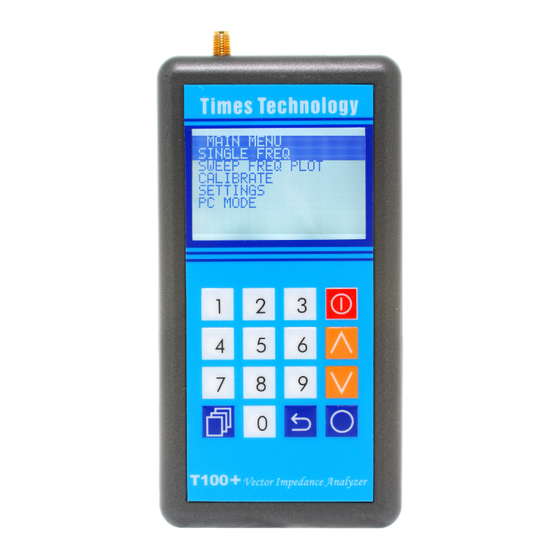
- Page 1 T100+ Vector Impedance Analyzer User Manual Ver. 2.1 T100+ is a state of the art portable Vector Impedance Analyzer. This powerful yet handy instrument is specifically designed for the advanced amateur radio experimenters working at the VHF and UHF bands. timestechnology.com.hk...
-
Page 2: Table Of Contents
Table of Contents GENERAL DESCRIPTION......3 T100+ MENU STRUCTURE.......4 KEY DEFINITIONS......5 SINGLE FREQ........7 SWR........7 IMPEDANCE (SERIES)......7 IMPEDANCE (PARALLEL)......8 S11........8 SWEEP FREQ PLOT......9 CALIBRATION.......10 SETTINGS........12 PC MODE........14 FIRMWARE UPDATE......16 T100+ SPECIFICATIONS......18 ACCESSORIES.......19 timestechnology.com.hk... -
Page 3: General Description
GENERAL DESCRIPTION T100+ Vector Impedance Analyzer is a device to measure complex impedance at VHF/UHF frequencies. This is accomplished by injecting an RF signal into the target under test connected to the SMA test port, and measuring the amplitude and phase of the reflected RF signal. -
Page 4: T100+ Menu Structure
T100+ MENU STRUCTURE MAIN MENU SINGLE FREQ •SWR •IMPEDANCE (SERIES) •IMPEDANCE (PARALLEL) •S11 (RECTANGULAR & POLAR) SWEEP FREQ PLOT •SWR •IMPEDANCE (Z) •RESISTANCE (R) •REACTANCE (X) •RETURN LOSS (S11) •PHASE ANGLE CALIBRATE •CONNECT OPEN •CONNECT SHORT •CONNECT LOAD SETTINGS •BACKLIGHT - AUTO - ON - OFF... -
Page 5: Key Definitions
KEY DEFINITIONS POWER : Press and hold this key for two seconds to turn on or off T100+ Vector Impedance Analyzer. CONFIRM : Use this key to confirm the desired selections and frequencies entered. MODE : In SINGLE FREQ, this key is used to switch between the following modes cyclically: •... - Page 6 be selected with the MODE key. NUMERICS : Use these keys to enter the desired frequency directly. Frequencies within the valid operating range will automatically be aligned to the 25KHz steps. Frequencies outside the valid operating range will be ignored. BACK : Cancel the current operation and/or go back to the previous menu.
-
Page 7: S11
SINGLE FREQ In this mode, T100+ can display the measured data in any of the following four representations. You may switch cyclically through these representations with the MODE key. •SWR •IMPEDANCE (SERIES) •IMPEDANCE (PARALLEL) •S11 (RECTANGULAR & POLAR) This mode displays the Standing Wave Ratio in large font for easy reading. - Page 8 displayed according to the sign of the reactance. IMPEDANCE (PARALLEL) This mode displays the impedance seen from the test port. The impedance is resolved into the real (resistive) part and imaginary (reactive) part connected in parallel. The corresponding inductance or capacitance is also displayed according to the sign of the reactance.
-
Page 9: Sweep Freq Plot
SWEEP FREQ PLOT Under this menu, T100+ can plot any of the following measured data over the desired frequency range: •SWR •IMPEDANCE (Z) •RESISTANCE (R) •REACTANCE (X) •RETURN LOSS (S11) •PHASE ANGLE Use the MODE key to switch cyclically between any of the following parameters to change their value. -
Page 10: Calibration
CALIBRATION T100+ Vector Impedance Analyzer employs industrial standard Open/Short/Load (OSL) calibration method to eliminate various system errors. To perform accurate measurements, T100+ needs to be calibrated against the OPEN, SHORT, and LOAD standards. Three high quality OPEN, SHORT, and LOAD SMA terminators are included for this purpose. - Page 11 Calibration data will be locked again automatically after calibration. The instrument is now ready to use. If desired, T100+ can be re-calibrated at any time. timestechnology.com.hk...
-
Page 12: Settings
SETTINGS A number of general options and information are available in this menu. BACKLIGHT AUTO - Turn off backlight automatically if no key is pressed for 30 seconds. ON - Leave backlight always on OFF – Leave backlight always off AUTO POWER OFF ENABLE –... - Page 13 BATTERY Choose between ALKALINE and NIMH to reflect the type of batteries being used. It only affects the threshold voltage dictating when a low battery sign on the upper right hand corner of the display will appear. CAL DATA PROTECT Select UNLOCK CAL DATA before calibration.
-
Page 14: Pc Mode
PC MODE T100+ has a build-in USB bridge (CP2102) by Silicon Labs (Silabs) and is capable of communicating with a PC via an emulated serial link over this USB connection. will need to install a Virtual COM Port (VCP) driver before connecting your T100+ to a PC. - Page 15 To command T100+ to tune to a specific frequency, the host program shall transmit a six-digit frequency in ASCII characters via the serial port. To command T100+ to take a measurement, send an ASCII character ‘S’. Then receive from the serial port a null terminated ASCII string.
-
Page 16: Firmware Update
FIRMWARE UPDATE T100+ firmware can be updated as new releases are available. Updated firmware file can be downloaded from our web site http://www.timestechnology.com.hk to a PC and be programmed to the T100+ via the USB interface. You will need to have the Virtual COM Port (VCP) driver installed before you can update the firmware via USB. - Page 17 On a PC running Windows XP/Vista/7 operating system, open a Command Prompt in a directory with the two files update.exe and firmware.ENC (available on our web site http://www.timestechnology.com.hk) *You may need to execute the Command Prompt as Administrator. Plug in the USB cable to connect the PC and T100+.
-
Page 18: T100+ Specifications
T100+ SPECIFICATIONS Frequency Range 100MHz ~ 170MHz (VHF) 400MHz ~ 470MHz (UHF) All PLL Synthesized Frequency Resolution: 25KHz Output Power : > 0dBm (typical) Harmonics : < -30dB (typical) Test Port Connector : SMA (female) Display : 128 x 64 dots graphical LCD with backlight Physical Dimensions : 140mm(length) x... -
Page 19: Accessories
ACCESSORIES SMA connector for OPEN Calibration: P/N 202112 SMA connector for SHORT Calibration:P/N 132331 SMA connector for LOAD Calibration: P/N 132360 SMA male to BNC female adapter SMA male to SO-239 adapter USB A to mini-B cable Windows is a registered trademark of Microsoft Corporation in the United States and other countries.
Need help?
Do you have a question about the T100+ and is the answer not in the manual?
Questions and answers