
Related Manuals for Times Technology T100

Summary of Contents for Times Technology T100
- Page 1 T100 Vector Impedance Analyzer timestechnology.com.hk User Manual Ver. 1.1 From The N3UJJ.COM Document Library From The N3UJJ.COM Document Library...
-
Page 2: General Description
T100 is a state of the art portable Vector Impedance Analyzer. This powerful yet handy instrument is specifi cally designed for the advanced amateur radio experimenters working at the VHF/UHF band. TABLE OF CONTENTS General Description T100 Menu Structure Key Defi nitions... - Page 3 T100 MENU STRUCTURE MAIN MENU SINGLE FREQ •SWR •IMPEDANCE (SERIAL) •IMPEDANCE (PARALLEL) •S11 (RECTANGULAR & POLAR) SWEEP FREQ PLOT IMPEDANCE RESISTANCE REACTANCE RETURN LOSS (S11) PHASE ANGLE CALIBRATE CONNECT OPEN CONNECT SHORT CONNECT LOAD SETTINGS BACKLIGHT AUTO AUTO POWER OFF...
-
Page 4: Key Definitions
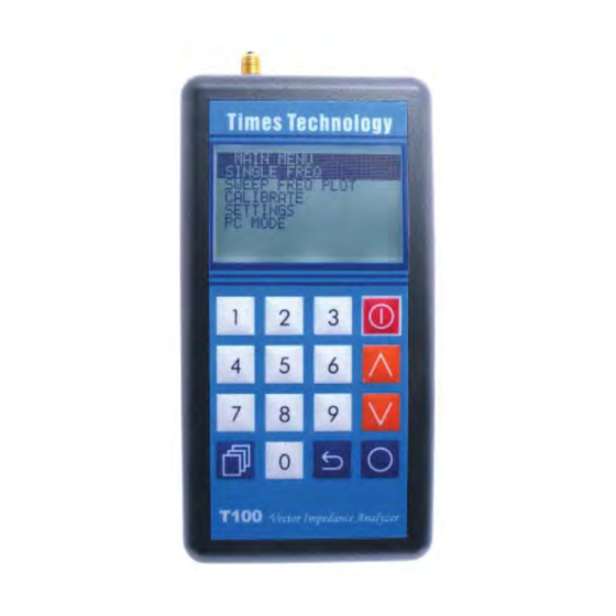
KEY DEFINITIONS POWER : Press and hold this key for two seconds to turn on or off T100 Vector Impedance Analyzer. CONFIRM : Use this key to confi rm the desired selections and fre- quencies entered. MODE : In SINGLE FREQ, this key is... - Page 5 ARROWS : These keys are used to se- lect the desired menu items or op- tions. They are also used to in- crease/decrease the frequency. Hold to increase/decrease frequency auto- matically. In SINGLE FREQ, the step size is fi xed at 25KHz. In SWEEP FREQ PLOT, the current step size can be selected with the MODE key.
-
Page 6: Single Freq
SINGLE FREQ In this mode, T100 can display the measured data in any of the following four represen- tations. You may switch cyclically through these representations with the MODE key. •SWR •IMPEDANCE (SERIAL) •IMPEDANCE (PARALLEL) •S11 (RECTANGULAR & POLAR) SWR displays the... -
Page 7: Impedance (Parallel)
IMPEDANCE (PARALLEL) IMPEDANCE displays the impedance FREQ:435025 seen from the test port. The impedance 240.10 - j194.53 is resolved into the real (resistive) part 1.88pF and imaginary (reac- PARALLEL tive) part connected in parallel. The cor- responding inductance or capacitance is also displayed according to the sign of the reac- tance. -
Page 8: Sweep Freq Plot
SWEEP FREQ PLOT Under this menu, T100 can plot any of the fol- lowing measured data over the desired frequen- cy range: •SWR •IMPEDANCE •RESISTANCE •REACTANCE •RETURN LOSS (S11) •PHASE ANGLE Use the MODE key to switch cyclically between any of the following parameters to change their value. - Page 9 Open/Short/Load (OSL) cali- bration method to eliminate various system errors. To perform accurate measurements, T100 needs to be calibrated against the OPEN, SHORT, and LOAD standards. Three high qual- ity OPEN, SHORT, and LOAD SMA terminators are included for this purpose.
- Page 10 SETTINGS SETTING MENU BACKLIGHT A number of general AUTO POWER OFF options and informa- BATTERY tion are available in CAL DATA PROTECT this menu. INFO BACKLIGHT BACKLIGHT MENU AU TO - Turn off AUTO backlight automat- ically if no key is pressed for 30 seconds.
- Page 11 LOCK CAL DATA to lock calibration data manu- ally if necessary. INFO SYSTEM INFORMATION Display general infor- MODEL : T100 mation of the device, H/W VER: 1.00 as well as the bat- F/W/VER: 1.00 tery voltage. BATTERY: blocks on the battery...
- Page 12 T100 from a PC, and displaying T100 mea- sured data. The (virtual) serial communication be- tween T100 and the PC should be confi gured as follows: Baud Rate = 38400 baud Parity Bit = None...
- Page 13 To command T100 to tune to a specifi c fre- quency, the host program shall transmit a six-digit frequency in ASCII characters via the serial port. To command T100 to take a measurement, send an ASCII character ‘S’. Then re-...
-
Page 14: Firmware Update
FIRMWARE UPDATE T100 fi rmware can be updated as new releases are available. Updated fi rmware fi le can be downloaded from the Internet to a PC and programmed to the T100 via the USB interface. Caution 1. Please use fresh batteries when updating fi... - Page 15 T100 SPECIFICATIONS Frequency Range: 100MHz ~ 170MHz (VHF) 400MHz ~ 470MHz (UHF) PLL Synthesized Frequency Resolution : 25KHz Test Port Connector : SMA Output Power : > 0dBm (typical) Harmonics : < -30dB (minimum) Display : 128 x 64 dots graphical LCD with backlight...
Need help?
Do you have a question about the T100 and is the answer not in the manual?
Questions and answers