
Subscribe to Our Youtube Channel
Related Manuals for Lectronics DM84

Summary of Contents for Lectronics DM84
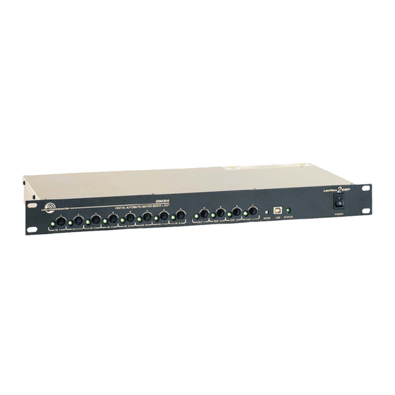
- Page 1 HARDWARE and SOFTWARE INSTALLATION GUIDE DM84 Digital Audio Processor Fill in for your records: Serial Number: Purchase Date: Rio Rancho, NM, USA www.lectrosonics.com...
- Page 2 DM84 Installation Guide LECTROSONICS, INC.
-
Page 3: Important Safety Instructions
DM84 Installation Guide Important Safety Instructions This symbol, wherever it appears, alerts you to the presence of uninsulated dangerous voltage inside the enclosure -- voltage that may be sufficient to constitute a risk of shock. This symbol, wherever it appears, alerts you to important operating and maintenance instructions in the accompanying literature. -
Page 4: Introduction
DM84 Digital Audio Proces- • Power cable sor, its components and software menus and setup screens. To get the most out of the DM84 system, it is • 6 each 5-pin de-pluggable connectors suggested to review the information presented in the •... -
Page 5: Table Of Contents
Introduction ................4 Unpacking the Unit ..............4 Items Included in the box: ............. 4 Hardware Installation ............. 6 Installing the DM84 System Into a Rack ....... 6 Audio Inputs ................. 6 Audio Outputs ............... 7 Programmable Inputs ............8 Programmable Outputs ............ -
Page 6: Hardware Installation
DM84 Installation Guide Hardware Installation Installing the DM84 System Into a Rack Audio Inputs The DM84 occupies a single rack space and there are Unbalanced Sources no special ventilation requirements. Mount with 4 rack Unbalanced audio sources (positive and ground) screws using the appropriate mounting holes. -
Page 7: Audio Outputs
DM84 Installation Guide Phantom Power The DM84 supplies +15 VDC phantom power to the Microphone Number 2: audio inputs via a programmable switch and two 2 k (min) = 9 V From Specification Sheet: resistors. (max.) = 2 mA = 15 V - (1k)(.002A) -
Page 8: Programmable Inputs
DM84 Installation Guide Programmable Outputs When the DM84 output is connected to a balanced input, wire it as shown here. Programmable outputs are used to indicate channel activity or the current state of a programmable input or some other feature of the DM84. Each programmable... -
Page 9: Expansion I/O Ports
DM84 Installation Guide DM84 Rear Panel LecNet 2 Programmable Expansion I/O Ports Inputs and Outputs Expansion I/O ports The four RJ45 connectors on the rear panel are used PROGRAMMABLE INPUTS/OUTPUTS to interconnect LecNet2™ units together. These ports 11- OUT 5... -
Page 10: Dani Bus Expansion I/O Ports
DM84 Installation Guide DANI Bus Expansion I/O ports The four RJ45 connectors on the rear panel are used to interconnect LecNet2™ units together. These ports are only used to transfer digital audio information via the Digital Audio Network Interface (DANI) between the DM Series processors that are interconnected. -
Page 11: Control System Interconnections
Control System Interconnections Part# 21529-1 (Black Cable) In addition to a Windows based computer system, ® the DM84 can be controlled by external serial control Device to PC system using the RS-232 interface, such as those from Crestron and AMX ®... -
Page 12: Installing Lecnet2 ™ Software And Usb Driver
DM84 Installation Guide Installing LecNet2 Software and USB Driver ™ Software Installer - Windows Installation The example shown her illustrates the installation pro- Or use the flash drive supplied with the processor. cedure using a Windows operating system. The screens that appear at each step using another operating sys- tem will vary, but the general steps are very similar. - Page 13 DM84 Installation Guide 3. The End User License Agreement screen 5. Click on Next to complete the installation. appears. Click on I Agree to continue. When the installation is complete, the confirmation screen will appear. 4. The installer will automatically download to a folder on your PC, or you can choose which folder it should be stored in.
-
Page 14: Usb Driver Installer
DM84 Installation Guide USB Driver Installer - Windows Installation Or use the flash drive The example shown her illustrates the installation pro- supplied with the processor. cedure using a Windows operating system. The screens that appear at each step using another operating sys- tem will vary, but the general steps are very similar. - Page 15 DM84 Installation Guide 4. The End User License Agreement screen appears. Click on I Agree to continue. 5. The installer will walk you through installation. When complete, the final screen will appear. Click on Finish to close the installation. Rio Rancho, NM...
-
Page 16: Initial Setup
DM84 Installation Guide Initial Setup The initial setup of a DM84 system is a relatively simple three step process: connect the unit to the computer, turn on the computer and select the appropriate control panel, preset the input, matrix and output. This process assumes that LecNet2™... -
Page 17: Initial Setup Hints
Matrix The gain of input and output audio channels is adjust- able from the front panel of the DM84. This feature is useful for system setup and adjustment, and may be left enabled to allow users to “touch up” gains as needed during operation. - Page 18 DM84 Installation Guide Service and Repair If your system malfunctions, you should attempt to correct or isolate the trouble before concluding that the equipment needs repair. Make sure you have followed the setup procedure and operating instructions. Check the interconnect- ing cables and then go through the TROUBLESHOOTING section in this manual.
- Page 19 DM84 Installation Guide Rio Rancho, NM...
- Page 20 DM84 Installation Guide LIMITED ONE YEAR WARRANTY The equipment is warranted for one year from date of purchase against defects in materials or workmanship provided it was purchased from an authorized dealer. This warranty does not cover equipment which has been abused or damaged by careless handling or shipping.
Need help?
Do you have a question about the DM84 and is the answer not in the manual?
Questions and answers