Table of Contents
Advertisement
Quick Links
9800 Martel Road
Lenoir City, TN 37772
www.ps-engineering.com
PAR200A
With Trig Avionics TY91 (L) or TY92 (L)
Document P/N 200-228-0200
Rev. 4, December 2017
Audio Selector Panel with VHF Communications Transceiver and
High-fidelity Stereo Intercom
System Installation and Operation Manual
Patented under one or more of the following;
No. 4,941,187; 5,903,227; 6,160,496 and 6,493,450
FAA-TSO C139, TSO C169a (PARTIAL)
EASA ETSO C139, 2C169A (PARTIAL)
The product warranty is not valid unless this product is installed by an
Authorized PS Engineering dealer.
PS Engineering, Inc. 2017 ©
Copyright Notice
Any reproduction or retransmittal of this publication, or any portion thereof, without the expressed written permission of PS En-
gineering, Inc. is strictly prohibited. For further information, contact the Publications Manager at PS Engineering, Inc., 9800
Martel Road, Lenoir City, TN 37772. Phone (865) 988-9800, email contact@ps-engineering.com.
Advertisement
Table of Contents

Related Manuals for PS Engineering PAR200A


Summary of Contents for PS Engineering PAR200A
- Page 1 Any reproduction or retransmittal of this publication, or any portion thereof, without the expressed written permission of PS En- gineering, Inc. is strictly prohibited. For further information, contact the Publications Manager at PS Engineering, Inc., 9800 Martel Road, Lenoir City, TN 37772. Phone (865) 988-9800, email contact@ps-engineering.com.
-
Page 2: Table Of Contents
Table of Contents Section I – GENERAL INFORMATION......... 1-1 INTRODUCTION ..........................1-1 SCOPE .............................. 1-1 EQUIPMENT DESCRIPTION ....................... 1-1 APPROVAL BASIS — FAA TSO, EASA ETSO ................1-2 1.1.1 PAR200A ......................... 1-2 1.1.2 T TY91/92-S : ..................... 1-2 ERIES SPECIFICATIONS .......................... 1-2 EQUIPMENT SUPPLIED ....................... - Page 3 PS Engineering Inc. ® PAR200A Audio Selector Panel, COM radio Controller and Intercom System Installation and Operator’s Manual 2.14 ........................2-14 NSTALLATION 2.15 ......................2-14 PERATIONAL HECKOUT 2.15.1 TY91/92 C ..................... 2-14 HECKOUT 2.15.2 TELEPHONE C .................... 2-15 HECKOUT 2.16 ........................
-
Page 4: Section I - General Information
Pushbutton switches select one of the communication transceivers for the pilot and copilot positions, and allow radio transmission. In "Split Mode”, the PAR200A has the ability to allow the pilot to transmit on Com 1 while the copilot can transmit on Com 2. A fail-safe mode connects the pilot headphone and microphone to COM 1 if power is removed for any reason, or if the power switch is placed in the Off (Fail-safe) position. -
Page 5: Approval Basis - Faa Tso, Easa Etso
Systems and Equipment). The VHF Communication Transceiver portion of the PAR200A is EASA author- ized under ETSO-2C169a. EASA.IM.210.10053809. The partial TSO applies to C169a because the PAR200A unit provides control and display only for the TY91- series of VHF communications equipment. - Page 6 PS Engineering Inc. ® PAR200A Audio Selector Panel, COM radio Controller and Intercom System Installation and Operator’s Manual Audio Selector Specifications 510 Audio selector panel input impedance: Input Isolation: -60 dB (min.) Receiver Inputs: 4 (Com 1, Com 2, Nav 1, Nav 2)
-
Page 7: Equipment Supplied
PS Engineering Inc. ® PAR200A Audio Selector Panel, COM radio Controller and Intercom System Installation and Operator’s Manual TY92L VHF Transceiver Specifications Radio Type Amplitude Modulation (AM) Aircraft Transceiver Channels (Transmit & receive) 760 channels, 25KHz spacing 2280 channels, 8.33 kHz spacing 118.000 –... -
Page 8: Equipment Required But Not Supplied
TNC Crimp Connector 425-400-1223 EQUIPMENT REQUIRED BUT NOT SUPPLIED Circuit Breaker: 1 ea; 3 amp PULL TYPE REQUIRED for PAR200A Circuit Breaker: 1 ea; 5 amp PULL TYPE REQUIRED for transceiver power (to TY91/92) Headphone Jacks (up to 4 Stereo, as Required) Microphone Jacks (up to 4 as Required) Headphones, 150 ... -
Page 9: Section Ii - Installation
Section 1.6 (B). If any claim is to be made, save the shipping material and contact the freight carrier. Do NOT return units damaged in shipping to PS Engineering. If the unit or acces- sories show any sign of external shipping damage, contact PS Engineering to arrange for a replacement. -
Page 10: Trig Ty91/Ty92 Mounting Requirements
There must be at least 13.8 VDC present at the connector, J2 pins 8 & 9, of the PAR200A for the power supply to work in its designed regulation. Otherwise, it cannot adequately attenuate power line noise. -
Page 11: Audio Panel Tray And Connector Assembly
PAR200A. The power for IFE and audio panel should be a common bus. -
Page 12: Ty91/92 Vhf Com Interface
Interfacing the TY91/92(L) as Single, COM 1 or COM 2 The PAR200A/ Trig TY91/92(L) can be configured to be a stand-alone COM, or as COM 1 or COM 2 in a multiple radio installation. In this case, PS Engineering recommends that the PAR200A/TY91/92(L) be used as COM 2. -
Page 13: Ty91/92 Tnc Antenna Connection
PS Engineering Inc. ® PAR200A Audio Selector Panel, COM radio Controller and Intercom System Installation and Operator’s Manual Avoid routing the cable round tight bends. Avoid kinking the cable even temporarily during installation. Secure the cable so that it cannot interfere with other systems. -
Page 14: Telephone (Duplex) Function For Bluetooth ® Capable Cell Phones
If Bluetooth connections become unreliable or do not connect, you may need to reset the PAR200A. Turn the PAR200A off, press & hold the N1 & N2 buttons while turning the unit back on, continue to hold the N1 & N2 for 3 seconds. -
Page 15: Telephone Sidetone
(your side of the telephone conversation) in the factory configuration. Some telephones al- ready provide sidetone, and the PAR200A can be configured to disable internal sidetone by placing the DIP switch in the proper configuration. Authorized PS Engineering installers should contact the factory for in- structions. -
Page 16: Intercom Wiring
IntelliPAX Expan- sion unit. See wiring diagram in §8.1. Music comes from the sources in the PAR200A and all intercom volume is controlled by the PAR200A inner volume control. -
Page 17: Music Inputs
28. Music #1 is available to the pilot and copilot positions, only, in normal configuration. Music 1 can be heard by all aircraft occupants, if Music 1 all headsets is activated with a switch connected to the PAR200A. See §2.7.2.1 Music 2 is only heard by the passengers. -
Page 18: Microphone Gain Reduction
For installations in very noisy aircraft, a reduction in the intercom microphone input gain might be desirable. The PAR200A has two DIP switches located on the main board that can switch the inputs to a lower gain setting. PS Engineering installers call for the Service Aid. -
Page 19: Communications Antenna Installation Notes
It is probable that radio interference will occur in the split mode when the frequencies of the two air- craft radios are adjacent, and/or the antennas are physically close together. PS Engineering makes no expressed or implied warranties regarding the suitability of the PAR200A in Split Mode. - Page 20 PAR200A Audio Selector Panel, COM radio Controller and Intercom System Installation and Operator’s Manual 2.11.2.1 Channel Assignment under 8.33 kHz spacing: The following table provides an example of the 8.33 Channel assignments as displayed on the PAR200A, when in the 8.33 mode. Bandwidth (kHz) Frequency Displayed 118.00000...
-
Page 21: Par200A Pin Assignments
PS Engineering Inc. ® PAR200A Audio Selector Panel, COM radio Controller and Intercom System Installation and Operator’s Manual 2.12 PAR200A Pin assignments Function Function No Connect Pilot Phones Low No Connect Copilot Phones Low No Connect Copilot Phones (L) No Connect... -
Page 22: Post Installation Checkout
2.14 Unit Installation To install the PAR200A, gently slide the unit into the mounting rack until the hold-down screw is engaged. While applying gentle pressure to the face of the unit, tighten the 3/32" hex-head in the center of the unit until it is secure. -
Page 23: Telephone Checkout
Verify that the cables are not exposed to any sharp edges or rough surfaces, and that all contact points are protected from abrasion. Return completed warranty registration application to PS Engineering, or complete online at www.ps-engi- neering.com. 200-228-0200 Page 2-15 Rev. -
Page 24: Section Iii Operation
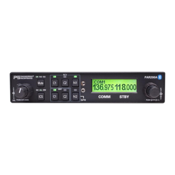
Figure 3-1 PAR200A Operating controls The following is divided into sections covering the basic operating areas of the PAR200A systems. They are Communications Transceiver Selection, Audio Selector, Intercom, VHF COM, music, telephone, and dis- play. -
Page 25: Communications Transmit (Xmt) Selection (2)
Com 2 transmitter pushbutton turns green. This guarantees that the pilot will always hear the audio from the transceiver selected for trans- mit. The PAR200A “remembers” the receiver selection, so that when switching transmitters from C 1 to C 2, if C 2 audio was previously selected, C 1 audio will continue to be heard. -
Page 26: Vhf Transceiver Control (5)
Figure 3-2 Cockpit Speaker Control 3.7 VHF Transceiver control (5) The right side of the PAR200A is dedicated to control of the VHF communications transceiver. Frequency selection is always directed to the STANDBY side of the display. To defeat the automatic radio squelch, push and hold the frequency-select knob until ASQ OFF is displayed on the screen Press again until ASQ ON and this will re-enable the radio squelch. -
Page 27: Radio Squelch
PS Engineering Inc. ® PAR200A Audio Selector Panel, COM radio Controller and Intercom System Installation and Operator’s Manual Figure 3-4 Frequency storage Turn the small knob to select the location (1 through 5). Push the small knob again, and the display will revert, and the frequency is stored in that location. -
Page 28: Tuning 8.33 Khz Channel Spacing
8.33 kHz spacing. This will be displayed on the LCD screen. Figure 3-8 Channel Spacing switching 3.7.4.1 Channel Assignment under 8.33 kHz spacing: The following table provides an example of the 8.33 Channel assignments as displayed on the PAR200A, when in the 8.33 mode. Bandwidth (kHz) -
Page 29: Intercom Operation (8)
The pilot and copilot positions work with stereo or mono headsets. All passenger headsets are connected in parallel. Therefore, if a monaural headset is plugged in to a PAR200A Stereo installation, one channel will be shorted. Although no damage to the unit will occur, passengers with stereo headsets will only hear in one ear, unless they switch to the “MONO”... -
Page 30: Intercom Modes (8)
This process will be necessary for any phone to be used, and only one cell phone can be associated with the audio panel at a time. If the additional phones are associated with the PAR200A at the same time, only the first phone will transfer audio to the panel. -
Page 31: Music Inputs
Violation of this rule could result in suspension of service and/or a fine. 3.10 Music Inputs The PAR200A has two independent music inputs at the rear connector. The PAR200A also has the ability to receive streaming music from a Bluetooth-enabled device. If both inputs are active, both will be heard in the headset at the same time, there is not any prioritization. - Page 32 PS Engineering Inc. ® PAR200A Audio Selector Panel, COM radio Controller and Intercom System Installation and Operator’s Manual of the mode selected. MUTE ON - music will mute with either intercom or radio – MUTE ON button is lit. RADIO MUTE – Intercom will not mute music, radio will mute music. RAD LED indicator is on INTERCOM MUTE - Radio will not mute music, intercom will mute music - MUTE ICS LED is ON.
-
Page 33: Section Iv - Warranty And Service
PS Engineering, Inc. warrants this product to be free from defect in material and workmanship for a period of two (2) years from the date of sale. During the two-year warranty period, PS Engineering, Inc., at its option, will send a replacement unit at our expense if the unit should be determined to be defective after consultation with a factory technician. -
Page 34: Appendix A - External Ptt Hook Up
PS Engineering Inc. ® PAR200A Audio Selector Panel, COM radio Controller and Intercom System Installation and Operator’s Manual Appendix A – External PTT Hook Up Part of the installation includes the installation of PTT (Push to Talk) switches that allow the use of your aircraft radio for communications transmissions. -
Page 35: Appendix B - Par200A Installation Drawings
PS Engineering Inc. ® PAR200A Audio Selector Panel, COM radio Controller and Intercom System Installation and Operator’s Manual Appendix B – PAR200A Installation Drawings Ground Lug 475-440-0001 (x2) Back plate assy 475-440-0001 (x2) Screw w/washer 475-009-0001 Viewed from Back ground lug (x2) -
Page 36: Ty91/92 Radio Installation Drawings
PS Engineering Inc. ® PAR200A Audio Selector Panel, COM radio Controller and Intercom System Installation and Operator’s Manual Tray and cutout dimensions Ca ut io n : Ap p l y s tead y p res s ur e to t he b eze l wh ile s cre wi n g t he u n it i nt o t he tra y to en s ur e e ve n s eat i n g o f t he u n it a nd co n n ec to rs . -
Page 37: Appendix C - J1 Connector Interconnect
PS Engineering Inc. ® PAR200A Audio Selector Panel, COM radio Controller and Intercom System Installation and Operator’s Manual Appendix C – J1 Connector Interconnect Figure 7-1 J1 connections, TY91/92(L)-05 as COM 2 PAR200A Connector, J1 (Sub-D 44-pin, male on tray) -
Page 38: Appendix D - J2 Connector Interconnect
PS Engineering Inc. ® PAR200A Audio Selector Panel, COM radio Controller and Intercom System Installation and Operator’s Manual Appendix D – J2 Connector Interconnect Pil ot Ph one s (R ) Pilot Pil ot Ph one s (L ) Phones... -
Page 39: Expansion Unit Interconnect (050-228-0202 Only)
PS Engineering Inc. ® PAR200A Audio Selector Panel, COM radio Controller and Intercom System Installation and Operator’s Manual 8.1 Expansion Unit Interconnect (050-228-0202 ONLY) PAR200A J2 Expans ion Unit 11636R Expansion Audio Input Expansion Lo Expansion Power PAR200A J1 Expansion Audio Output (L) -
Page 40: Appendix E - Instructions For Faa Form 337 And Continuing Airworthiness
Aircraft equipment list, weights and balance amended. Compass compensation checked. A copy of the operation instruc- tions, contained in PS Engineering document 202-228-( ), revision ( ), dated ( ), is placed in the aircraft records. All work accomplished listed on Work Order 9.2 Instructions for Continuing Airworthiness, Audio System... -
Page 41: Appendix F - Rtca Do160G Environmental Qualification Form
PS Engineering Inc. ® PAR200A Audio Selector Panel, COM radio Controller and Intercom System Installation and Operator’s Manual Appendix F – RTCA DO160G Environmental Qualification Form Audio Selector Panel/Intercom/Communications Transceiver Controller Part Number: 050-228-( FAA TSO Number: C139, C169a EASA ETSO C139, 2C169a...
Need help?
Do you have a question about the PAR200A and is the answer not in the manual?
Questions and answers