
Related Manuals for QUAD EZ-4000

Summary of Contents for QUAD EZ-4000
- Page 1 Owner and Installation Manual For: EZ-4000 LOW ENERGY AUTOMATIC SWING DOOR OPERATOR PLEASE READ THIS ENTIRE MANUAL AND FOLLOW ALL GUIDELINES TO ENSURE PROPER INSTALLATION AND SAFETY PROUDLY DISTRIBUTED BY… REV. 12_6_16 - 1 -...
- Page 2 READ THIS FIRST! Quick Start Guide Caution: When used in a low energy installation, the EZ-4000 operator and associated ES500 control must be installed and adjusted in accordance with ANSI 156.19. Warning: The ES500 control must remain connected to the operator at all times.
- Page 3 CAUTION An improperly installed and/or adjusted Automatic Door can cause injury and equipment damage. Door must be installed and adjusted as described in this Owner’s Manual by a certified professional. All required safety devices must be in place and operational. Door must be inspected DAILY.
- Page 4 There is no expressed or implied warranty by Quad Systems, LLC except as specifically stated above. Quad Systems, LLC shall not be liable for special or consequential damage, nor for claims of any third party against the buyer. NOTE: Quad Systems, LLC units are identified by serialized numbers (stamps or stickers) and recorded by sales purchase order numbers, date sold, date made and date tested.
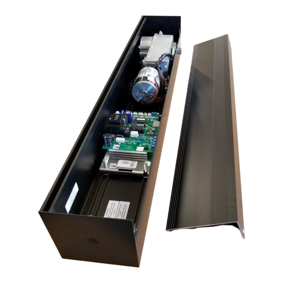
- Page 5 WARNING: The EZ-4000 may be used for Residential or Commercial interior doors only with widths up to 48" (1220 mm) and a maximum weight of 350 lb. (91 kg). The operator can open the door up to an opening angle of 110°...
- Page 6 NOTE: If door is an In-Swing, allow 8” minimum between header and opposing wall to allow clearance for the Pull Arm. Step Two-Mounting Operator-Controller Move square nuts provided in header slots to pre-marked positions. Lift unit into header and secure with the 4 bolts provided making sure output shaft is at center of opening.
- Page 7 BUTT HINGE OR OFFSET PIVOT REVEAL IN-SWING OUT-SWING DIM “A” DIM “B” DIM “A” DIM “B” 13” (33cm) 10” (25cm) 16” (41cm) 17 ¼” (44cm) ½” (13mm) 13” (33cm) 10” (25cm) 16” (41cm) 17 ½” (44cm) 1” (25mm) 13” (33cm) 10”...
- Page 8 Out-Swing In-Swing - 8 -...
- Page 9 ES-500 Swing Control Installation WARNING: When used in a low energy installation, the EZ-4000 operator and associated ES500 control must be installed and adjusted in accordance with ANSI 156.19 documentation. WARNING: The ES500 control must remain connected to the operator at all times. Never leave the operator without a control connected, as the closing speed will be uncontrolled and may cause severe damage to the operator or door.
- Page 10 ground wire must be connected to the frame of the operator using the ground screw provided in the junction box. Restore power via the building circuit breaker, but do not plug the line power harness into the control yet. The actuating devices, plus any optional devices, will be wired in a later step. If a lock is present, temporarily disable it to keep it from jamming the door while setting up the operator.
- Page 11 SPD (latch speed) pots for the desired closing operation. The door may be manually opened as many times as necessary to complete these adjustments. 1.4 Opening Adjustments Physically inspect the open check switch (switch with orange and yellow wires) and its associated cam.
- Page 12 The control directly supports the use of automatic locks of either the mortise or magnetic type. An optional lock harness must be obtained from Quad Systems. If a lock is to be used, wire it to the lock harness as shown in the diagram. Typically, the normally closed relay contact is used with magnetic locks, and the normally open contact for mortise strikes.
- Page 13 the optional stop-n-seek safety device, if used. The normal display sequence during a cycle is OS – d1 (or d2) – OC – HO, then CL – LC – Id. 1.7 Parameter List The following list shows all adjustable parameters in the ES500 control, along with a brief description of their function and their factory default values.
- Page 14 devices (the devices are ignored when the door is closed). Setting AF to 3 allows this connection to be used for a safety beam input. Other values of AF are reserved and disable the CN7 input when selected. ct Cycle Test. This cycles the door at regular intervals for testing. Default is off. PG Push And Go.
- Page 15 EZ-4000 Power Consumption The measured currents and power consumptions for the EZ-4000 operator are as follows: -Idle, door closed: 0.066 amperes, 8 watts -Opening, operator only (no door attached), peak measurement: 0.46 amperes, 56 watts -Holding open: 0.265 amperes, 32 watts The opening power will be somewhat higher with a door attached to the operator.
- Page 16 - 16 -...
- Page 17 - 17 -...
- Page 18 Lock with No Transformer (not recommended) Lock with Transformer (recommended) - 18 -...
- Page 19 It is often the function of an accessory device called a "lockout relay" to block the sensor signal while the door is closing. However, the Quad System ES-500 control does not require a separate lockout relay, as it has the lockout feature built in.
- Page 20 BEA Technical Support East Region 866.836.1863 West Region 888.419.2564 - 20 -...
- Page 21 Optex Technical Support 800-966-7839 - 21 -...
- Page 22 904C Optex Technical Support 800-966-7839 - 22 -...
- Page 23 - 23 -...
- Page 24 C4160-2, C4190, or C7160-3 controls. An adapter harness would be required to allow the EZ-4000 to plug into the Horton control. The harness would have the proper connectors on each end and would also include the brown wire for the open check micro-switch, which Horton's C7160-3 control requires (Quad Systems ES-500 control does NOT require this connection, so it is not present in the current operator wiring harness).
- Page 25 Q. I am using the operator in a high energy mode. How can I acquire support for a safety beam per ANSI 156.10? A. Although Quad Systems does not recommend the use of this operator and/or control in a high energy mode, this feature is supported beginning in Versions 1.02/1.03. An auxiliary harness (Close Monitor harness, (part number 600-0008-01) will be required.
- Page 26 - 26 -...
Need help?
Do you have a question about the EZ-4000 and is the answer not in the manual?
Questions and answers