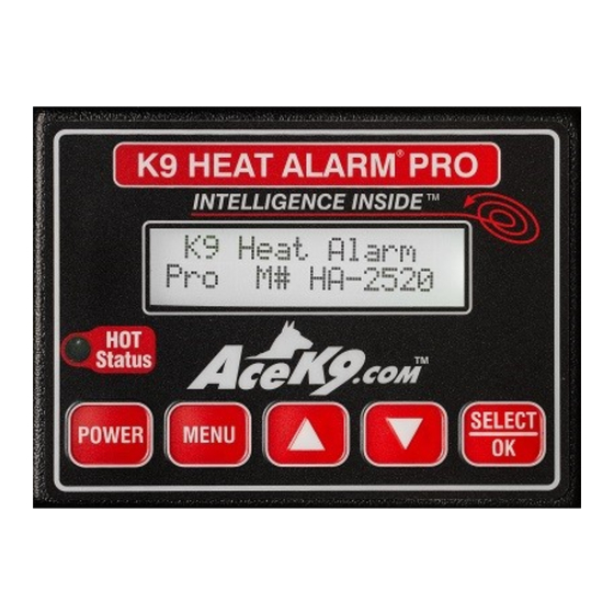
Ace K9 HA-2520 Installation Manual

With protective relay module

Advertisement

Quick Links

Model HA-2520
Patent # 7,081,811
K9 Heat Alarm
Pro
®
With Protective Relay Module
Installation Manual
Refer to the vehicle specific instructions sheet during install.
Life Safety Equipment
It is vital that all Safety Features are installed, tested and working properly.
Special Attention needs to be made to Power and Safety Warnings.
This Life Safety Equipment must be installed to Emergency Vehicle Up-
fitting Standards!
Radiotronics Inc.
1315 SW Commerce Way
Stuart Fl 34997
Phone: (772) 600-7574
Fax (772) 600-7012
www.AceK9.Com

Advertisement

Table of Contents
loading

Summary of Contents for Ace K9 HA-2520

  • Page 1 Model HA-2520 Patent # 7,081,811 K9 Heat Alarm ® With Protective Relay Module Installation Manual Refer to the vehicle specific instructions sheet during install. Life Safety Equipment It is vital that all Safety Features are installed, tested and working properly.
  • Page 2 Contents Warnings and Safety information Introduction Page 1 Safety Information Page 2 Installation Page 3 Step 1 Planning Page 3 Step 2 Control Head installation Page 3 Step 3 Intelabox installation Page 3 4 Protective Relay Module Connections Page 4 Battery power Ground PRM to IntelaBox...
  • Page 3: Safety Warnings

    This manual is used in conjunction with the vehicle specific instructions sheet. If the make, model and year do not match the vehicle instructions or the equipment is being reinstalled in new vehicle Contact AceK9.Com Service Department. When contacting AceK9 service, have your SERIAL NUMBER available. ________________________________________________________________________________________ Safety Warnings and Installation Information Life Safety Equipment...
  • Page 4: Installation

    Installation This manual is written to provide the information necessary for safe and reliable operation of Read the Vehicle Specific Instructions this Life Safety Equipment. to guide you thru the install. STEP 1 Planning Consult with the end user  Determine a suitable mounting location for the Control Head. The Head should be easily visible to the K9 Handler.
  • Page 5: Battery Power

    STEP 4 Protective Relay Module (PRM) Connections The Protective Relay Module is the output controller for heat alarm options and accessories.  Locate the Protective relay module near the Intelabox.  Connect the IntelaBox Heat Alarm Option Cable (Gray Cable with black connector) to Protective Relay Module (PRM).
  • Page 6 Connecting outputs from the Protective Relay Module The Protective Relay Module Provides output wires to activate standard horn, lights, and siren activation, and the window drop feature. To accommodate a variety of setups a choice of low current ground triggers or positive activation are provided.
  • Page 7: Step 5 Horn Alert Feature

    STEP 5 Horn Alert Feature A Choice of Positive or Negative Outputs are provided  Consult your Vehicle Specific Information for horn polarity , wire color, and connection location  When other equipment is attached to the horn wire, always place the K9 connection closest to the horn.
  • Page 8: Step 6 Lightbar / Strobe Alert

    STEP 6 Light Bar/Strobe Alert Feature “TIP” Some Light/Siren Controllers allow for programming of both light and siren activation off one input. A Choice of positive or negative output is provided. AceK9 Wire Color: Green (-) Green/Red (+) Green wire provides a negative output (Low Current Ground Trigger 0.75A) Green/Red wire provides a positive output (12V+ when triggered Fused at 15A Max) Light Controler Input Method...
  • Page 9: S Tep 8 Window Drop Feature

    STEP 8 Window Drop Feature Refer to Vehicle Specific Instructions for window down wire colors and locations. Using the vehicle specific information as a guide, follow the instructions packed with your window drop module. The Protective Relay Module’s Blue/Red wires supply power to the Window Drop Modules.
  • Page 10 STEP 10 Heat Alarm Ignition Power Red/Yellow (pin 7) From the Protective Relay Module connect the Red/Yellow Ignition wire to the police package ignition point, or switched Ignition Power point on the Vehicle’s fuse panel. Ignition must be connected for proper operation of K9 Heat Alarm ®...
  • Page 11 (32 ◦ c), The Stall monitor should be enabled only if a stall sensor has installed. To review or change these settings enter Menu mode See the User Guide. Test Procedure for K9 Heat Alarm Pro HA-2520 1) Power. The Default Power Settings is Heat Alarm ON with Ignition. When Ignition is turned ON, the Heat Alarm will power up.
  • Page 12: Trouble Shooting

    Trouble Shooting Communications Error, no power to head, Display flickers and beeps continuously. Check Control head cable for damage Check that connectors are fully inserted Check that cable is not running parallel to transmitting antennas On units that have been in service, check for corrosion or foreign material. Check power and ground to the PRM and that the IntelaBox is plugged in to the PRM.
  • Page 13 Blank Page K9 Heat Alarm Pro Protective Relay With Module INSTALL MANUAL...

This manual is also suitable for:

Heat alarm pro

Table of Contents