Onkyo TX-DS797 Service Manual
Black, golden and silver models
Hide thumbs
Also See for TX-DS797:
- Brochure & specs (28 pages) ,
- Instruction manual (76 pages) ,
- Instruction manual (76 pages)
Advertisement
Quick Links
Download this manual
See also:
Instruction Manual
SERVICE MANUAL
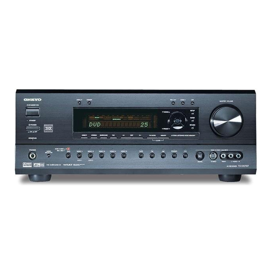
AV RECEIVER
TX-DS797
MODEL
DISPLAY
DIMMER
STANDBY/ON
STANDBY
POWER
ON
OFF
DIRECT
STEREO
SURROUND
THX
UPSAMPLING
ZONE
2
(
GRN
)
PHONES
REC
(
RED
)
AUDIO
DVD
VIDEO 1
VIDEO 2
VIDEO 3
VIDEO 4
VIDEO 5
SELECTOR
VCR 1
VCR 2
Black, Golden and Silver models
BMDD
BMPP,SMPP,BMPA,GMPA
BMWT,GMWT,GMWR
GMGT
SAFETY-RELATED COMPONENT
WARNING!!
COMPONENTS IDENTIFIED BY MARK
SCHEMATIC DIAGRAMS AND IN THE PARTS LIST ARE
CRITICAL FOR RISK OF FIRE AND ELECTRIC SHOCK.
REPLACE THESE COMPONENTS WITH ONKYO
PARTS WHOSE PART NUMBERS APPEAR AS SHOWN
IN THIS MANUAL.
MAKE LEAKAGE-CURRENT OR RESISTANCE
MEASUREMENTS TO DETERMINE THAT EXPOSED
PARTS ARE ACCEPTABLY INSULATED FROM THE
SUPPLY CIRCUIT BEFORE RETURNING THE
APPLIANCE TO THE CUSTOMER.
REC OUT
ZONE
2
OFF
MASTER VOLUME
SETUP
TUNI NG
ENTER
RE TURN
PRESET
DSP
FM MODE
MEMORY
A-FO RM LISTENING MODE MEMORY
CLEAR
VIDEO
5
/VIDEO CAM INPUT
TAPE
FM
AM
PHONO
C D
DIGITAL
S VIDEO
VIDEO
120V AC, 60Hz
230-240V AC, 50Hz
120/220-230V AC, 50/60Hz
220-230V AC, 50Hz
ON THE
TX-DS797
Ref. No. 3714
102001
L
AUDIO
R
797
TX-DS
AV RECEIVER
Advertisement

Related Manuals for Onkyo TX-DS797


Summary of Contents for Onkyo TX-DS797
-
Page 1: Service Manual
COMPONENTS IDENTIFIED BY MARK ON THE SCHEMATIC DIAGRAMS AND IN THE PARTS LIST ARE CRITICAL FOR RISK OF FIRE AND ELECTRIC SHOCK. REPLACE THESE COMPONENTS WITH ONKYO PARTS WHOSE PART NUMBERS APPEAR AS SHOWN IN THIS MANUAL. MAKE LEAKAGE-CURRENT OR RESISTANCE... -
Page 2: Specifications
TX-DS797 SPECIFICATIONS AMPLIFIER SECTION TUNER SECTION Continuous Average Power output (FTC) All channels: 100 watts per channel min. RMS at Tuning Range: 87.5 — 108.0 MHz (50 kHz steps) 8 ohms, 2 channels driven from 20 Usable Sensitivity Hz to 20 kHz with no more than Mono: 11.2 dBf, 1.0 u V (75 ohms IHF) - Page 3 TX-DS797 SERVICE PROCEDURES 1. Replacing the fuses 4. Memory Preservation This unit does not require memory preserv ation batteries. A This symbol located near the fuses indicates that the built-in memory power back-up system preserv es the contents fuse used is fast operating type. For continued protection against of the memory during po wer f ailures and even when the unit is fire hazard, replace with same type fuse.
- Page 4 TX-DS797 WIRING VIEW 1 9-2 shows the number of schematic diagram. NAETC-7272 RI NAAR-7267 P811A P2805A terminal PC board Connector PC board P2705A P2006A NAAF-7262 P5003E JL931A Preamplifier circuit PC board P2901B P4020A P3010A P2505A 4-1,4-2 P6832B P6830B P2905A P3210A...
- Page 5 TX-DS797 WIRING VIEW 2 9-2 shows the number of schematic diagram. NAETC-7239 NASW-7235 Thermal detector P917 Power switch PC board NAETC-7236 P918A circuit PC board NAETC-7272 P917A Speaker terminal P6810D P6008A RI terminal F/C PC board P6012A P6830 JL931A PC board...
- Page 6 TX-DS797 BLOCK DIAGRAM D I G I T A L A U D I O I N P U T O P T I C A L 1 1 d B M U L T I C H A N N E L I N P U T...
- Page 7 TX-DS797 BLOCK DIAGRAM 1 D I G I T A L A U D I O I N P U T O P T I C A L R X 0 V I D E O 5 S B R...
- Page 8 TX-DS797 BLOCK DIAGRAM 2 1 1 d B M U L T I C H A N N E L I N P U T M U T E S B R S B L 1 1 d B H E A D P H O N E...
- Page 9 TX-DS797 MICROPROCESSOR CONNECTION VIEW D 6 6 0 3 F R O N T C H . S U R R O U N D C H . Q 2 9 1 0 , 1 1 MAIN MICROPROCESSOR V O L U M E...
- Page 10 TX-DS797 MAIN MICROPROCESSOR Terminal Descriptions No. Function Act. Description Function Act. Description BYTE Input pin to change the width of external data bus. Connect to Vss. ADR152 Signal output pin to control address 15 of flash memory for second DSP.
- Page 11 TX-DS797 MAIN MICROPROCESSOR CONNECTION DIAGRAM 1 F R O N T C H . D 6 6 0 3 S U R R O U N D C H . V O L U M E V O L U M E...
- Page 12 TX-DS797 MAIN MICROPROCESSOR CONNECTION DIAGRAM 2 D 6 6 0 3 Q 2 9 1 0 , 1 1 1 2 V T o B U S R L 6 6 0 3 T R I G G E R...
- Page 13 TX-DS797 SUBMICROPROCESSOR-CONNECTION DIAGRAM P 7 4 8 1 H E A D P H O N E S H P D E T D 7 5 3 4 Q 7 5 3 4 IN/OUT R E D G R E E N...
- Page 14 TX-DS797 SUBMICROPROCESSOR Terminal Descriptions No, Function Descriptions No, Function Descriptions FLOSDDA O Serial data output pin for FL tube driver and OSD IC. 50 LEDGRE Power supply control output pin for zone 2 indicator FLOSDCL O Serial clock output pin for FL tube driver and OSD IC.
- Page 15 TX-DS797 ADJUSTMENT AND CONFIRMATION PROCEDURES 1 Idling current adjustment Before Idling adjustment, turn the trimming resistors R6040,R6041,R6042,R6043,R6044 and R9046 to counter clockwise. Connect the DC voltmeter to sockets P6080,P6081,P6082,P6083,P6084 and P6086. After turn POWER to ON, adjust the trimming resistors R6040, R6041 and R6042 so that the reading of voltmeter becomes 7.0 mV.
- Page 16 TX-DS797 ADJUSTMENT AND CONFIRMATION PROCEDURES 2 3. Confirmation of Current detection circuit Set the unit to "TEST-1-00". Connect the differentiating circuit and apply the 200Hz square signal to MULTI CHANNEL INPUT terminal. of each channel. Adjust the attenuator or Volume so that the output level becomes 35V p-p.
- Page 17 . Note: No input signal. The segments of odd number light on . AA:Model "89":TX-DS898 "79":TX-DS797 "AA BB CC DD EE" BB:Video Mode "NS": NTSC "PL": PAL AUTO light on. CC:12V TRIGGER "TR": Available " ":No available DD:RDS "RD": Available "...
- Page 18 TX-DS797 EXPLODED VIER Front panel section P7201...
- Page 19 TX-DS797 EXPLODED VIEW P901 P1010 73 72 P7201 75 71 F901 F902 F903 P7701 Q6062 F9501 F9504 F6902 F9503 Q6066 F6901 T901 F9502 Q6056 Q6050 E821...
- Page 20 TX-DS797 EXPLODED VIEW-PARTS LIST REF. NO. PART NO. DESCRIPTION REF. NO. PART NO. DESCRIPTION Front bracket <B> 27175319A 27111248 Front bracket <S> 28141332 27111249 Cushion Front bracket <G> 831430088 3TTW+8B(BC),Self-tapping screw 27111250 Retainer HP 27141787 27122906 Rear panel <D> 838430088...
- Page 21 TX-DS797 EXPLODED VIEW-PARTS LIST REF. NO. PART NO. DESCRIPTION REF. NO. PART NO. DESCRIPTION T901 NPT-1421D,Power transformer <D> 1A906541-1N NAETC-7241-1N,PC board for holder <D> 2301536 NPT-1421P,Power transformer <P/A> 1A906541-1O NAETC-7241-1O,PC board for holder <P> 2301537 NPT-1421DG,Power transformer <WT/R/GT> 1A906541-1P NAETC-7241-1P,PC board for holder <R>...
- Page 22 TX-DS797 EXPLODED VIEW-PARTS LIST 3 REF. NO. PART NO. DESCRIPTION 1A906531-1A NASW-7331-1A,Volume PC board ass'y <D> 1A906531-1B NASW-7331-1B,Volume PC board assay <B> <P> 1A906531-1C NASW-7331-1C,Volume PC board ass'y <B> <A> 1A906531-1D NASW-7331-1D,Volume PC board ass'y <B> <WT> 1A906531-1E NASW-7331-1E,Volume PC board ass'y <G> <GT/A>...
- Page 23 TX-DS797 EXPLODED VIER Rear panel section P901 P1010 73 72 75 71 F901 F902 F903...
- Page 24 TX-D S7 9 7 SCHEMATIC DIAGRAM 1 Display section TO NAAR-7267 (Part-9) FROM M-BOARD P7201A NADIS-7330 R7276 R7277 R7376 R7377 Q7501 MPA/MGT 16-BT-96GNK MWR/MWT 12.0 C7501 C7518 REGION MDD,MJJ OTHER C7519 474Z R7289 223Z 223Z COUNTRY MDD,MPP OTHER R7501 220 R7389 P7481 SILVER...
- Page 25 TX-DS797 SCHEMATIC DIAGRAM 2 I N T R E Q 1 DSP & Main T O N A A R 7 2 6 7 I N T R E Q 2 P 7 7 0 4 B F L A S H W R I T E R...
- Page 26 TX-DS898 SCHEMATIC DIAGRAM 3 Audio I/O section P 1 0 1 0 A T O T U N E R P A C K P 3 2 2 0 A V I D E O 5 N A A F - 7 2 6 3 N A A F - 7 2 6 4 * P a r t N o .
- Page 27 TX-DS797 SCHEMATIC DIAGRAM 4 Preamp. section C 4 2 0 0 N A A F - 7 2 6 2 1 0 / 5 0 C 4 8 0 2 C 4 8 0 0 C 4 4 0 0...
- Page 28 TX-DS797 SCHEMATIC DIAGRAM 5 Power amp.section N A A F - 7 2 5 1 N A A F - 7 2 3 2 R 5 3 0 3 5 6 . 2 V R 5 3 0 0 5 6 . 2 V...
- Page 29 TX-DS797 SCHEMATIC DIAGRAM 6 Power amplifier section 2 N A A F - 7 2 5 0 R 6 2 3 0 R 6 2 7 0 1 2 0 R 6 0 8 0 Q 6 0 3 3 Q 6 0 0 3 1 .
- Page 30 SCHEMATIC DIAGRAM 7 Power supply, Fan control & Speaker terminal sections P / W / G - T Y P E P / W / G - T Y P E C 9 2 2 N A E T C - 7 2 3 6 N A P S - 7 2 3 3 P 6 8 0 0 N A E T C - 7 2 3 7...
- Page 31 TX-DS797 SCHEMATIC DIAGRAM 8 Video section N A V D - 7 2 6 8 N A V D - 7 2 6 9 R 2 4 0 3 7 5 2 S C 2 7 1 2 G R...
- Page 32 TX-DS797 SCHEMATIC DIAGRAM 9 Componet video and mother sections N A A R - 7 2 6 7 N A E T C - 7 2 7 2 I R I N , R I , N A V D - 7 2 7 0...
- Page 33 TX-DS797 PRINTED CIRCUIT BOARD VIEW FROM SOLDERING SIDE B 2 Soldering side A: Parts & Patterns Soldering side B: Patterns OOOOOOO ############ X7701 L104 R7830 P812 R7829 R7826 Q720 P7701A C7711 Q706 R7801 C7711 P102A P813 R7802 P7702 C156 D7701...
- Page 34 TX-DS797 PRINTED CIRCUIT BOARD VIEW FROM SOLDERING SIDE 3 C1003 C1006 P3200 C1002 C1007 Q1001 P3201 P3202 P3203 P3220A P3200 P3201 P3202 P3203 C3012 C3013 C3010 C3011 J357 C3009 C3008 J356 J354 J353 J351 J352 J324 C3122 J317 J326 C3403...
- Page 35 TX-DS797 PRINTED CIRCUIT BOARD VIEW FROM SOLDERING SIDE 7 P9503 RISK OF FIRE -REPLACE FUSE AS MARKED. J5525 J5529 J6738 C6909 P6802 J5524 J5528 P9505A J6739 J5523 J5527 J6741 P6951 J5209 J5202 J6735 J5212 J5205 C6853 C6855 J6740 P6802 P6951...
- Page 36 TX-DS797 PRINTED CIRCUIT BOARD VIEW FROM SOLDERING SIDE 8 P2502 P2501 P2502 P2503 P2504 P2501 C2433 P2002 P2003 P2001 R2402 R2404 R2431 R2303 R2304 C2307 R2305 R2306 R2307 R2308 C2308 R2309 R2310 R2311 R2312 C2309 R2313 P2003 C2436 R2301 R2302...
- Page 37 TX-DS797 PRINTED CIRCUIT BOARD VIEW FROM SOLDERING SIDE B 9 C2907 P7201B Q2903 Q2902 P7704A P7705A P811A Q2904 NCAR-7267 P7703A Q2905 D2902 25137267B C2904 D2903 C2913 P4012A Q2906 Q2907 LOCK P9502 P4020A P4011A P4010A J2903 5.6S LOCK LOCK +13V DGND...
- Page 38 TX-DS797 PRINTED CIRCUIT BOARD VIEW FROM SOLDERING SIDE 1 Display section P7481 J7403 P7203 L7483 P7481 DIMMER DISPLY J7239 P7201A ZONE2 RECOUT S7573 S7559 J7254 C7205 NCDIS-7330 J7255 J7238 25137330B S7565 S7564 S7563 J7251 J7236 P7483 J7201 SETUP Q7501 J7237...
- Page 39 TX-DS797 PRINTED CIRCUIT BOARD VIEW FROM SOLDERING SIDE 1 Display section R7552 R7551 R7542 R7553 R7543 R7540 R7534 R7548 R7544 R7545 R7546 R7547 C7294 C7297 Q7521 Q7523 Q7530 Q7529 Q7531 Q7522 Q7524 Q7525 Q7527 Q7538 Q7526 Q7202 Q7539 Q7532 R7382...
- Page 40 TX-DS797 PRINTED CIRCUIT BOARD VIEW NCAF-7262 C4611 FROM SOLDERING SIDE 4 25137262A C4610 C4617 C4401 J4181 C4521 C4601 C4411 C4211 C4521 C4612 C4201 C4241 C4231 J4222B C4523 J4221A J4172 J4222A J4221B J4180 J4220B J4173 C4614 C4400 C4200 J4174 C4410 C4230...
- Page 41 TX-DS797 PRINTED CIRCUIT BOARD FROM SOLDERING SIDE 4 R4811 R4807 Soldering side Q4815 R4817 Q4813 R4813 Q4812 R4812 C4140 R3605 Q4814 R4712 R3615 R4710 R3806 R4702 R4711 R3606 R3625 R4700 R4806 R4701 C3681 R3616 R4022 R4605 R4615 R3603 R3626 R4032...
- Page 42 TX-DS797 PRINTED CIRCUIT BOARD VIEW FROM SOLDERING SIDE 5 P6014A P6016A P6015A P6013A J6002 J6011 J6016 J6025 P6006A P6005A P6004A P6003A P5202 P5001C P5001B P5001A P5001D R5296 C5066 R5295 C5065 R5294 C5064 R5293 C5063 R5006 R5005 R5004 R5003 C5056 C5055...
- Page 43 TX-DS797 CAUTION: Replacement for transistor of mark *, if necessary PRINTED CIRCUIT BOARD-PARTS LIST 1 must be made from the same beta group (H ) as the original type. MAIN CIRCUIT PC BOARD (NADG-7226-1N/1O/1R) CIRCUIT NO. PART NO. DESCRIPTION Coils CIRCUIT NO.
- Page 44 TX-DS797 PRINTED CIRCUIT BOARD-PARTS LIST 2 CIRCUIT NO. PART NO. DESCRIPTION CIRCUIT NO. PART NO. DESCRIPTION Diodes Resistors D5000-D5002 224470562 MTZJ5.6B R901 431533355 ! RC1/2GFKUL-3.3M <D> R924 443521804 18ohm+/-5%,1/2W,Metal oxide Capacitors C5000,C5001 393371017 100uF,63V,Elect. Relay C5002 393384707 47uF,50V,Elect. RL901 25065584,...
- Page 45 TX-DS797 PRINTED CIRCUIT BOARD-PARTS LIST 3 NOTE: <D>:120V model only <R> Chinese model only <P>:European model only <A>: Australian model only <WT>:Worldwide model only <O>: All models except 120V model <GT> 220V model only CIRCUIT NO. PART NO. DESCRIPTION SPEAKER TERMINAL SR/SB PC BOARD...
- Page 46 TX-DS797 PRINTED CIRCUIT BOARD-PARTS LIST 3 NOTE: <D>:120V model only <R> Chinese model only <P>:European model only <A>: Australian model only <WT>:Worldwide model only <O>: All models except 120V model <GT> 220V model only CIRCUIT NO. PART NO. DESCRIPTION SPEAKER TERMINAL SR/SB PC BOARD...
- Page 47 TX-DS797 PRINTED CIRCUIT BOARD-PARTS LIST 4 CAUTION: Replacement for transistor of mark *, if necessary must be made from the same beta group (H ) as the original type. CIRCUIT NO. PART NO. DESCRIPTION CIRCUIT NO. PART NO. DESCRIPTION Transistors...
- Page 48 TX-DS797 CAUTION: Replacement for transistor of mark *, if necessary PRINTED CIRCUIT BOARD-PARTS LIST 5 must be made from the same beta group (H ) as the original type. CIRCUIT NO. PART NO. DESCRIPTION CIRCUIT NO. PART NO. DESCRIPTION Terminals...
- Page 49 TX-DS797 PRINTED CIRCUIT BOARD-PARTS LIST 6 NOTE: <D>:120V model only NOTE: THE COMPONENTS IDENTIFIED BY MARK ! <O>: All models except 120V model ARE CRITICAL FOR RISK OF FIRE AND ELECTRIC SHOCK. REPLACE ONLY WITH PART NUMBER SPECIFIED. POWER SUPPLY CIRCUIT PC BOARD (NAPS-7252-2A/2B) CIRCUIT NO.
- Page 50 TX-DS797 PRINTED CIRCUIT BOARD-PARTS LIST 6 NOTE: <D>:120V model only NOTE: THE COMPONENTS IDENTIFIED BY MARK ! <O>: All models except 120V model ARE CRITICAL FOR RISK OF FIRE AND ELECTRIC SHOCK. REPLACE ONLY WITH PART NUMBER SPECIFIED. POWER SUPPLY CIRCUIT PC BOARD (NAPS-7252-2A/2B) CIRCUIT NO.
- Page 51 TX-DS797 PRINTED CIRCUIT BOARD-PARTS LIST 7 NOTE: <D>:120V model only <D>:120V model only <O>: All models except 120V model CIRCUIT NO. PART NO. DESCRIPTION CIRCUIT NO. PART NO. DESCRIPTION Terminals Capacitors C4491 374721024 1000pF+/-5%,50V,Plastic P3000,P3001 25045575 or NPJ-4PDRW389 or C4492 354724719 470uF,6.3V,Elect.
- Page 52 TX-DS797 PRINTED CIRCUIT BOARD-PARTS LIST 8 NOTE: <O>: All models except 120V model CIRCUIT NO. PART NO. DESCRIPTION CIRCUIT NO. PART NO. DESCRIPTION Resistors Coils R2912 453530474 4.7ohm+/-5%,1/2W,Metal L2001 231292J056R2 NCH-1572 R2913 453530224 2.2ohm+/-5%,1/2W,Metal L2002 231237K022R2 NCH-1471 Sockets Capacitors P4012A...
- Page 53 TX-DS797 PRINTED CIRCUIT BOARD-PARTS LIST CONNECTOR PC BOARD (NAETC-7273-1N/1O) CIRCUIT NO. PART NO. DESCRIPTION Sockets CIRCUIT NO. PART NO. DESCRIPTION P2501 25051750 NSCT-4P1537 Plugs P2502 25051568 NSCT-12P1355 P2007A,P2507A 25055712 NPLG-20P668 P2503,P2504 25051748 NSCT-8P1535 DISPLAY CIRCUIT PC BOARD (NADIS-7330-1A/1B/1C/1D/1E/1F/1G) P2505B 25051237...
- Page 54 TX-DS797 PRINTED CIRCUIT BOARD-PARTS LIST 10 CIRCUIT NO. PART NO. DESCRIPTION Sockets P7201A 25051877 NSCT-33P1664 P7482A 25051089 NSCT-5P876 P7559A 25051087 NSCT-3P874 Holder Q7501A 27191074A (FL) VOLUME PC BOARD (NASW-7331-1A/1B/1C/1D/1E/1F/1G) CIRCUIT NO. PART NO. DESCRIPTION S7569 25065575 EC16B2425,Rotary encoder P7559B 25051087...
- Page 55 TX-DS797 PACKING PROCEDURES 120V model Bottom Accessary bag PARTS LIST REF. NO. PART NO. DESCRIPTION 29092002 29100153 1020x720,Poly bag 29110098 Tape PP 29053790 Carton box S 29053815A Carton box 29362958A Label UPC 29365090 Warranty card 29100097-1A 350*250,Poly bag 29343204A Instruction manual E...
- Page 56 TX-DS797 PACKING PROCEDURES Other models Bottom Accessary bag 121 Accessary bag 122 REF. NO. PART NO. DESCRIPTION 29092002 29100153 1020x720,Poly bag 29110098 Tape PP 29053790 Carton box S 29053816A Carton box <B><P> 29053817A Carton box <B><WT/A> 29053818A Carton box <S>...
- Page 57 Sales & Product Planning Div. : 2-1, Nisshin-cho, Neyagawa-shi, OSAKA 572-8540, JAPAN Tel: 072-831-8111 Fax: 072-833-5222 ONKYO U.S.A. CORPORATION 18 Park Way, Upper Saddle River, N.J. 07458, U.S.A. Tel: 201-785-2600 Fax: 201-785-2650 E-mail: onkyo@onkyousa.com ONKYO EUROPE ELECTRONICS GmbH Industriestrasse 20, 82110 Germering, GERMANY Tel: 089-849-320 Fax: 089-849-3265 E-mail: info@onkyo.de...