
Related Manuals for AirSense 310e

Summary of Contents for AirSense 310e
- Page 1 AIRSENSE Model 310e Microprocessor-based, Infrared Environmental CO 2 Sensor Operator's manual © Copyright 2010...
- Page 2 AirSense Model 310e Operator’s Manual Date 12/1/02 9/9/2005 10/7/08 12/7/10 (V6) 2/9/11 (V7) 3/9/15 (V8) Digital Control Systems 3/9/15 Page:...
-
Page 3: Table Of Contents
AirSense Model 310e Operator’s Manual Table of Contents Introduction ................. 1 Displays and Indicators ............... 1 Specifications ................2 Installation ................... 3 Cover Removal ..............3 Mounting................3 Wiring ................... 4 Power Supply ..............4 Signal Output ..............4 Verifying Voltage or Current Output Connection ....5 Cover Replacement ............... -
Page 4: Introduction
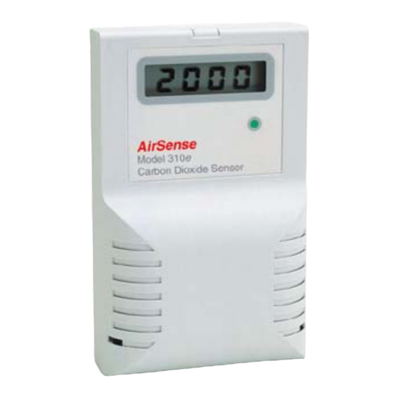
Model 310e simple to maintain. Displays and Indicators The basic Model 310e has a single green LED on the front panel which illuminates whenever the unit is operating. This LED is on steadily when the measured concentration is... -
Page 5: Specifications
AirSense Model 310e Operator’s Manual Specifications Operating principle Non-dispersive infrared (NDIR) Gas sampling method Diffusion or sample draw Measurement range 0 - 5000 ppm CO 2 ±75 ppm (@ 1200ppm) Typical drift (per year) ±5% of reading or ±75 ppm, Accuracy ±20 ppm... -
Page 6: Installation
Figure 1: AirSense Model 310e Mounting Dimensions Cover Removal To open the Model 310e use a coin in the slot on the bottom to release the snap. Lift the cover up slightly to disengage the closure and remove cover with a downward motion to clear the catch at the top of the unit. -
Page 7: Wiring
Signal Output The Model 310e provides either a 0 - 10 volt or a 4 - 20 mA current loop output at the two terminals of the analog output connector shown in Figure 2. -
Page 8: Verifying Voltage Or Current Output Connection
Verifying Voltage or Current Output Connection After the voltage or current output of the Model 310e is connected to a controller or indicator, the following check should be performed to ensure that the connection has been... -
Page 9: Cover Replacement
JP5 is closed, verify that the wiring is correct. 3. Remove the shorting block from JP4 and restore it to its original position at jumper JP5. The Model 310e will reset and it’s output now corresponds to the actual detected CO 2 concentration. -
Page 10: Field Adjustments
This section refers to advanced features of the Model 310e. 2000 ppm users need not perform this adjustment. The Model 310e ships from the factory set for an analog output range of 0 to 2000 ppm. This range can be changed... - Page 11 1000. 8. Remove the shorting block from JP4 and restore it to its original position at jumper JP5. The Model 310e will reset and its output will now only change when the gas concentration is within the range selected.
-
Page 12: Altitude Correction
AirSense Model 310e Operator’s Manual Altitude Correction The Model 310e is factory-calibrated for operation at sea level. When operated at higher elevations, the calibration must be adjusted by the ALTITUDE amount shown in the altitude CORRECTION TABLE correction table to the right. -
Page 13: Calibration
2000 ppm calibration gas is recommended A calibration kit is available from the factory. To verify the Model 310e's calibration, proceed as follows: 1. Remove the front cover of the unit (see procedure on page 3). -
Page 14: High Co2 Limit
High CO2 Limit An adjustable high CO limit is a standard feature of the model 310e. The front panel LED changes from steady to blinking when the indicated concentration is above the high limit value. An optional contact closure is available which opens or closes when the high limit is exceeded. -
Page 15: Optional High Limit Contact
AirSense Model 310e Operator’s Manual Optional High Limit Contact The high CO 2 limit option provides a dry (i.e. unpowered) contact closure that activates when the detected concentration rises above the high CO limit. The high limit is adjustable from 0 to full scale of the unit... -
Page 16: Duct Sampling Option
Minimum recommended flow rate is 200 feet per minute. A Model 310e with the duct sample option has a sample draw adapter fitted to the bottom of its enclosure. The duct probe assembly is connected to tubing nipples on the adapter. -
Page 17: Duct Kit Contents
4) Connect the open ends of the two tubes from the probe assembly to the two sample ports on the base of the Model 310e. It makes no difference which tube is connected to which port on the Model 310. -
Page 18: Disclaimers And Notices
Limited Warranty and Remedies. DCS warrants to Buyer of the AirSense Model 310e that for 18 months from the date of shipment of Products to the Buyer that Products will substantially conform with the product specifications agreed to by DCS. - Page 19 AirSense Model 310e Operator’s Manual THE WARRANTY IN THIS SECTION IS IN LIEU OF ALL OTHER WARRANTIES, EXPRESS OR IMPLIED. DCS EXPRESSLY DISCLAIMS ALL IMPLIED WARRANTIES, INCLUDING THE WARRANTIES OF MERCHANTABILITY AND FITNESS FOR A PARTICULAR PURPOSE. DCS IS NOT RESPONSIBLE...
Need help?
Do you have a question about the 310e and is the answer not in the manual?
Questions and answers