
Related Manuals for Getronic GT915

Summary of Contents for Getronic GT915
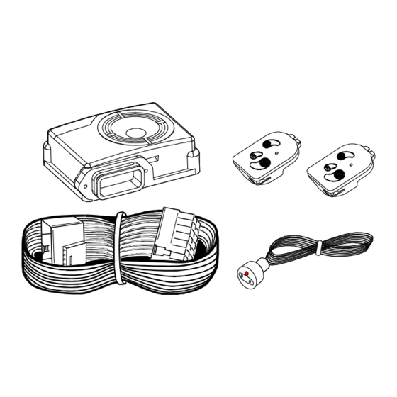
- Page 1 GT915/916/917/918 INSTALLATION AND USER MANUAL Getronic S.r.l. Via Calcinate No.12 21026 Gavirate (VA) Italy Tel. +39 0332 756011 Fax + 39 0332 731162 www.gtalarm.it...
-
Page 2: Table Of Contents
2.0 - INSTALLATION AND CONNECTIONS Page 3 3.0 - CONNECTION DIAGRAM Page 4 4.0 - INDICATOR COMMAND DIAGRAM Page 5 5.0 - GT931 ULTRASONIC KIT CONNECTION(only for GT915) Page 5 6.0 - CENTRAL DOOR LOCKING DIAGRAMS Page 6 7.0 - SET FUNCTIONS Page 8 8.0 - USER MANUAL... -
Page 3: Installation And Connections
2.0 - INSTALLATION AND CONNECTIONS WARNINGS: - Complete a pre-installation check and disconnect the negative terminal of the vehicle’s battery. . - Before fixing the device, insert the installation loom connectors into the alarm and screw the connector cover on. - Place the alarm system in the engine compartment, away from direct sources of water spray and high tension wiring. -
Page 4: Connection Diagram
The WHITE and GREY wires (Max. capacity 7 mA) are used for the engine immobilisation either on the diesel or petrol vehicles. Cut the ignition switched wire which supplies the fuel pump or electrovalve (diesel vehicles). Connect the two wires one to the GREY wire and the other to the WHITE one. -
Page 5: Indicator Command Diagram
ORANGE/BLACK 5.0 - GT931 ULTRASONIC MODULE CONNECTION (only x GT915)/917/ Install the two ultrasonic sensors on the “A” pillars (see pic below). One either side of the windscreen pointing towards a hypothetical point at the centre of the rear window and ensure that between the ultrasonics and the rear window there are no objects (i.e. -
Page 6: Central Door Locking Diagrams
6.0 - CENTRAL DOOR LOCKING DIAGRAMS DIAGRAM No.3 (Unlocking = 1" - Locking = 1") GT ALARM YELLOW/GREY RED/GREY COMMAND BUTTON YELLOW/BROWN 10 AMP FUSE YELLOW/BLUE CENTRAL DOOR RED/BROWN 10 AMP FUSE LOCKING ACTUATORS RED/BLUE POSITIVE COMMAND WHEN UNLOCKING POSITIVE COMMAND WHEN LOCKING DIAGRAM No.4/A (Unlocking = 1"... - Page 7 DIAGRAM No.5 (Unlocking = 1" - Locking = 1") GT 71 ACTUATOR GT ALARM YELLOW/GREY RED/GREY 5 AMP FUSE LIGHT BLUE RED/BLUE YELLOW/BROWN RED/BROWN YELLOW/BLUE DIAGRAM No.8 (Unlocking = 1" - Locking = 40”) GT ALARM AMP FUSES RED/BROWN RED/BLUE DO NOT CONNECT YELLOW/BLUE YELLOW/BROWN...
-
Page 8: Set Functions
7.0 - SET FUNCTIONS The system is equipped with a “SET FUNCTIONS” which allows to program and customize the alarm following to the user needs. To access to the SET FUNCTIONS: 1 - The alarm must be disarmed. 2 - Switch the vehicle ignition key on, place the GT888 handsets contacts to the receptacle and check that 5 quick beeps are emitted and the RED LED will switch on constant. - Page 9 SET FUNCTIONS TABLE FUNCTION STATE DESCRIPTION ENABLED DISABLED HANDSETS SELF-CODING RAPID TEST GREEN COMFORT CLOSINGS 1” unlock - 40” lock 1” unlock - 1” lock GREEN ACOUSTIC SIGNAL WHEN ARMING/DISARMING GREEN BLINKER COMMAND GREEN DOORS PIN SWITCH POLLING MANAGEMENT GREEN POSITIVE DOORS PIN SWITCH MANAGEMENT LEGEND: N = N = Function No.
- Page 10 - Function No. 2: RAPID TEST. With this function it is possible to check the correct installation carrying out a test of all the alarm connections. Additional modules entry test: triggering the sensor (ultrasonic microwaves, inclination etc.) the system generates 1 beep and No.1 GREEN flash of the del LED on the receptacle. DOORS pin switch test: opening one or more doors the system generates 4 beeps and 4 GREEN flashes of the LED on the receptacle.
-
Page 11: User Manual
8.0 - USER MANUAL - HANDSET DESCRIPTION. GT888 GT884N (Optional) PANIC GT888: 3 button handset with electronic key incorporated. GT884N: 1 multifunction button (Optional). ON-OFF - “ON/OFF”:button: to arm and disarm the alarm. - With automatic transmission selectable if required. DOUBLE ON/OFF LOCKING... - Page 12 LED starts to flash. The ignition key, boot/bonnet protection are active 5 seconds after arming, while the door pin switch and the additional input and the wires cut (only for GT915/916) are only active when the check status LED flashes. - PANIC FUNCTION (only with GT888).
- Page 13 RED/GREEN WIRES CUT Flashes without pause PAUSE (only for GT915/916) WARNING: - The signals sequence of occurred alarms and anomalies detected is repeated at each vehicle ignition key switching on. - The alarms system memory is deleted to the following the alarm system arming.
-
Page 14: Maintenance And Warnings
9.0 - MAINTENANCE AND WARNINGS MOTOR VEHICLEWASHING. It is necessary to pay particular attention to any source of water spray. It is advisable, during this operation to protect it with a covering (i.e. cellophane). - FUNCTIONS CHECK. To have an always efficient system it is advisable to carry a periodic check of all the functions. -
Page 15: Compliance Declaration
European Directive: R&TTE 1999/5/CE (including the directives: 95/54CE) All Getronic products are compatible with the vehicle’s original electronic systems. The GT888/884N handsets are in compliance with sthe following European Directives: EMCC DR. RASEC “Notified Body 0678”... -
Page 16: Warranty Conditions
12.0 - WARRANTY CONDITIONS - This Certificate should be kept in a safe place and produced for verification should technical assistance be required. Inability to produce this Certificate may affect your warranty rights. Warranty period bengins from date of purchase and is valid for 12 months (24 months for U.K.).
Need help?
Do you have a question about the GT915 and is the answer not in the manual?
Questions and answers