Table of Contents

Related Manuals for Waterway NEO 2100


Summary of Contents for Waterway NEO 2100
- Page 1 INSTRUCTION MANUAL SPA CONTROL SYSTEM Designed, Engineered & Manufactured in the USA. 2200 East Sturgis Road, Oxnard CA 93030 • Phone 805.981.0262 • Fax 805.981.9403 waterway@waterwayplastics.com • www.waterwayplastics.com 807-1930.0114 ©2014 Waterway Plastics...
- Page 2 SPA CONTROL SYSTEM SAVE THIS MANUAL PLEASE MAKE IT AVAILABLE TO ALL OTHER SPA USERS WARNING! Qualified Technician Required for Service and Installation BASIC INSTALLATION AND CONFIGURATION GUIDELINES • Use minimum 6AWG copper conductors only. • Readily accessible disconnecting means to be provided at time of installation. •...
- Page 3 CAUTION! CSA COMPLIANCE / CONFORMITÉ • Test the ground fault circuit interrupter before each use of the spa. • Read the instruction manual. • Adequate drainage must be provided if the equipment is to be installed in a pit. • For use only within an enclosure rated CSA Enclosure 3. •...
-
Page 4: Main Screen
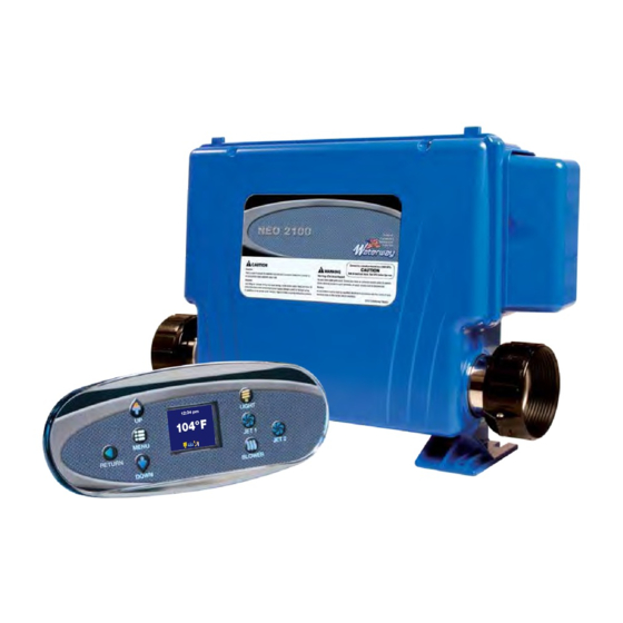
12:34 pm 104°F 1 2 3 LIGHT 12:34 pm JET 6 104°F DOWN JET 1 JET 5 JET 4 MENU JET 2 1 2 3 JET 1 JET 2 JET 3 RETURN BLOWER MAIN SCREEN: 12:34 pm The main screen displays current time, water temperature, and status of the system accessories. -
Page 5: Spa Operation
SPA OPERATION: Turn system accessories ON and OFF by pushing appropriate button on the right side of panel (LIGHT, JET 1, BLOWER, JET 2…) These accessories have timeout defaults from the manufacturer and will turn OFF automatically after the time has expired. Timeout time for LIGHT default is 60 minutes; BLOWER default is 15 minutes; JET at low speed default is 60 minutes;... -
Page 6: Panel Timeout
SELECTION ICONS: FILTER CYCLE 1 ENERGY SAVING HEAT MODE OZONE ON FILTER CYCLE 2 VACATION HEAT MODE JET ON LOW SPEED FILTER CYCLE 3 CLEANER CYCLE JET ON HIGH SPEED FILTER CYCLE 4 POLLING CYCLE BLOWER ON LIGHT ON TEMPERATURE LOCK SPECIAL TEMP SELECT HEATER ON PANEL LOCK... -
Page 7: Setting Screens
SETTING SCREENS: • ROTATE VIEW: rotate the view 180 degrees, the UP and DOWN button also swap when rotated. With ROTATE VIEW highlighted press MENU to enter ROTATE VIEW setting. Use UP/DOWN to select the desire setting and RETURN to exit and confirm the setting. -
Page 8: Error Screens
ERROR SCREENS: Error caused when SENSOR 1 and Plumbing Error Sensor 1 open SENSOR 3 have been plugged in incorrectly. Swap the SENSOR 1 and SENSOR 3 plug in controller to correct this problem. Check SENSOR 1 connection. Press RETURN to clear Press RETURN to clear Error caused by no water flow through heater Insufficient Flow... - Page 9 WIRING DIAGRAM (without Daughter Board)
- Page 10 WIRING DIAGRAM with Daughter Board (DB1)
- Page 11 WIRING DIAGRAM with Daughter Board (DB2)
- Page 12 WIRING DIAGRAM xxxxxxxxx)
Need help?
Do you have a question about the NEO 2100 and is the answer not in the manual?
Questions and answers
NEO-2100....Does leaving the cover open set off any sort of alarm?