Dickey-John GAC 2500 Operator's Manual
Hide thumbs
Also See for GAC 2500:
- Operator's manual (46 pages) ,
- Operator's manual (63 pages) ,
- Quick start manual & mobile app tutorial (31 pages)
Table of Contents
Advertisement
Quick Links
OPERATOR'S MANUAL
Safety Notices ..................................................................................................... 1
Disclaimer ......................................................................................................................... 1
Introduction ......................................................................................................... 3
Accessories ....................................................................................................................... 3
Unit Overview .................................................................................................................... 3
Features ............................................................................................................................ 4
Specifications .................................................................................................................... 4
Declaration of Conformity ................................................................................................. 4
External Communication Connections .............................................................................. 5
Printer ............................................................................................................................... 6
Quick Start Guide ................................................................................................ 7
Step 1: Unlock Shipping Brackets .................................................................................................... 7
Step 2: Instrument Placement .......................................................................................................... 8
Step 3: Leveling Instrument ............................................................................................................. 8
Step 4: Initial Setup .......................................................................................................................... 8
Step 5: Begin Grain Analysis ........................................................................................................... 9
Step 6: Select a Product .................................................................................................................. 9
Step 7: Perform a Grain Analysis ................................................................................................... 10
Physical Instrument Setup ............................................................................... 11
Unlock Shipping Brackets ............................................................................................... 11
Instrument Placement ..................................................................................................... 14
Leveling Instrument ........................................................................................................................ 14
Security .............................................................................................................. 15
OEM Password ............................................................................................................... 16
Installation ......................................................................................................... 17
Connecting AC Power ..................................................................................................... 17
Grain Drawer ................................................................................................................... 18
Optional Bottomless Grain Drawer ................................................................................................. 18
Initial Setup ........................................................................................................ 19
Navigation .......................................................................................................... 21
Using External Devices ................................................................................................... 21
Touch Screen Button Functions ...................................................................................... 21
Home .............................................................................................................................................. 21
Power Off ....................................................................................................................................... 22
Initiate ............................................................................................................................................. 22
Print ................................................................................................................................................ 22
Back ............................................................................................................................................... 22
Abort ............................................................................................................................................... 22
Enter ............................................................................................................................................... 22
USB ................................................................................................................................................ 22
User ................................................................................................................................................ 22
Instrument Information ................................................................................................................... 22
LCD Display Touch Screen Calibration .......................................................................................... 22
Keypad ........................................................................................................................................... 23
Clean .............................................................................................................................................. 23
Region ............................................................................................................................................ 23
Import Region ................................................................................................................................. 23
Delete Region ................................................................................................................................ 23
11001-1655B-201611
/ I
Advertisement
Table of Contents

Related Manuals for Dickey-John GAC 2500


Summary of Contents for Dickey-John GAC 2500
-
Page 1: Table Of Contents
OPERATOR’S MANUAL Safety Notices ..................... 1 Disclaimer ......................... 1 Introduction ......................3 Accessories ........................3 Unit Overview ........................3 Features ..........................4 Specifications ........................4 Declaration of Conformity ....................4 External Communication Connections ................5 Printer ..........................6 Quick Start Guide ....................7 Step 1: Unlock Shipping Brackets .................... - Page 2 OPERATOR’S MANUAL Password Restrictions ..................25 Setup ......................... 27 Product ........................... 27 Edit Existing Product ........................27 Edit Product ............................ 29 Create Product ..........................30 Delete Product ..........................31 Load New Product ......................32 Administrative Settings ....................34 To Change a Known User Name/Password ................... 34 System Setup .........................
- Page 3 OPERATOR’S MANUAL Results ....................... 77 Refine Query Options ..................... 78 Unable to Show Query Results ..................79 Audit Trail ........................80 View Products ......................... 82 Grain Calibrations ..................... 83 Diagnostics ......................85 Maintenance ...................... 87 External Cleaning ......................87 Internal Cleaning ......................88 Daily Clean Method ........................
- Page 4 OPERATOR’S MANUAL GAC® 2500 Model (INTL) 11001-1655B-201611...
-
Page 5: Safety Notices
DISCLAIMER DICKEY-john reserves the right to make engineering refinements or procedural changes that may not be reflected in this manual. Material included in this manual is for informational purposes and is subject to change without notice. - Page 6 We rigorously test and calibrate each instrument before it leaves the factory. Use of the instrument in the field, however, is subject to environmental and operating conditions beyond our control. DICKEY-john disclaims all liability for damages resulting from environmental and...
-
Page 7: Introduction
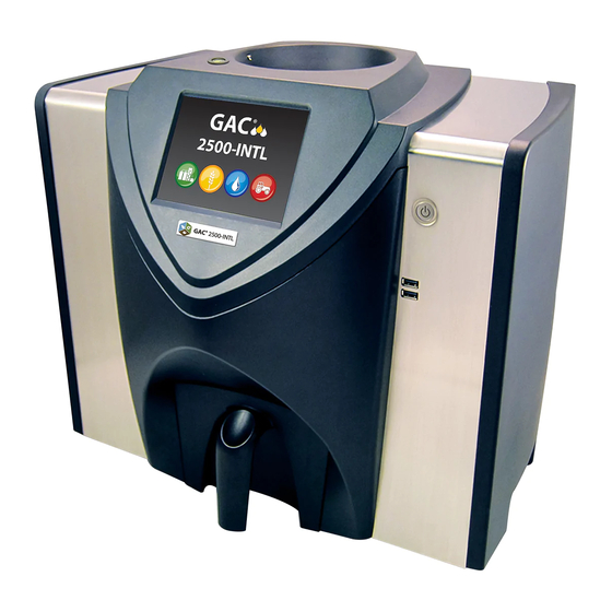
OPERATOR’S MANUAL INTRODUCTION ® The DICKEY-john Grain Analysis Computer GAC 2500-INTL quickly tests grain and automatically calculates moisture content, temperature, and test weight (bulk density) of the sample. The unit prompts for sample loading, tests the sample, and displays the results. -
Page 8: Features
OPERATOR’S MANUAL FEATURES • Color touch screen display guides users through testing and setup • Easy-to-use user interface • Fast, accurate grain analysis • Alpha/numeric sample identification with the ability to add an optional extended keyboard or bar code reader via USB •... -
Page 9: External Communication Connections
OPERATOR’S MANUAL EXTERNAL COMMUNICATION CONNECTIONS • 4 USB connections (2 in front, 2 in back) to connect a keyboard, NOTE: A USB memory device less than or equal to 2-4 GB in size mouse, printer or flash drive. Up to 3 devices can be active on USB. formatted as FAT is ®... -
Page 10: Printer
OPERATOR’S MANUAL PRINTER An optional printer that is RS232 compatible or a USB printer that supports ® Printer Control Language (PCL) can connect to the GAC 2500 to print test data results to a ticket. The ticket can be setup to include the facility name and address, product, date and time, sample ID, customer ID, grain calibration date, percent moisture, grain temperature, test weight, and errors. -
Page 11: Quick Start Guide
OPERATOR’S MANUAL QUICK START GUIDE This section details the basic steps of setup and analyzing using the GAC 2500 INTL instrument. Refer to other sections of this manual for more detailed instructions. STEP 1: UNLOCK SHIPPING BRACKETS Two shipping brackets must be unlocked prior to setup and operation. 1. -
Page 12: Step 2: Instrument Placement
Keyboard Style Standard then proceed to Main QWERTY Menu. Thank you for purchasing your GAC2500-INTL from DICKEY-john. The next screens will take you through some basic setup steps for your new GAC2500-INTL. Set Region Region QUICK START GUIDE GAC® 2500 Model (INTL) -
Page 13: Step 5: Begin Grain Analysis
The Main Menu screen appears Power Instrument after all Startup screens have Information loaded. This is the “Home” menu DICKEY-john Corporation DICKEY-john Corporation through which all other menus are Current User: UserName accessed. 1. Press the Analyze button to Analyze... -
Page 14: Step 7: Perform A Grain Analysis
OPERATOR’S MANUAL STEP 7: PERFORM A GRAIN ANALYSIS 1. If enabled, the Enter Sample NOTE: Drawer capacity holds Enter Sample ID Enter Sample ID approximately 3 tests. After 3 ID screen appears. The selected Product: Corn tests the drawer must be product and Issue ID displays at Issue ID: 070109 emptied before proceeding. -
Page 15: Physical Instrument Setup
OPERATOR’S MANUAL PHYSICAL INSTRUMENT SETUP UNLOCK SHIPPING BRACKETS ® The GAC 2500 instrument contains (2) shipping brackets that secure the measurement cell during shipping. After unpacking the instrument, the shipping brackets must be unlocked and placed in the operating location before proceeding to setup and operation. - Page 16 OPERATOR’S MANUAL Figure 6 Loosen Hex Bolt from Bracket 6. Remove hex bolt and set aside. Figure 7 Remove Hex Bolt 7. Press down on the bracket to release. Figure 8 Press Down on Bracket PHYSICAL INSTRUMENT SETUP GAC® 2500 Model (INTL) 11001-1655B-201611...
- Page 17 OPERATOR’S MANUAL 8. Slide bracket forward and align with operating location. Figure 9 Slide Bracket Forward 9. Insert hex bolt into operating location hole and securely tighten using the Allen wrench. Figure 10 Insert Hex Bolt and Tighten 10. Perform the same procedure to the other bracket. 11.
-
Page 18: Instrument Placement
OPERATOR’S MANUAL INSTRUMENT PLACEMENT Place the instrument in a clean environment that is protected from rapid changes in ambient temperature and vibration. Avoid a hazardous (classified) location as defined in Article 500 of the NFPA Handbook of the National Electrical Code. •... -
Page 19: Security
IMPORTANT: Some INTL machines are also equipped with a seal that covers the security switch. Check with DICKEY-john Technical Support group or your local service center before breaking the seal. When the switch is toggled from secure to unsecure, an event is logged into memory for traceability. -
Page 20: Oem Password
OPERATOR’S MANUAL SECURITY GAC® 2500 Model (INTL) 11001-1655B-201611... -
Page 21: Installation
Unit Dimensions during transit. Save all packing TOP VIEW materials until inspection is 16.2” complete. If damage is found, file a claim with the carrier immediately and notify your DICKEY-john sales representative. 10.5” 18.6” 13.9” 16.9” SIDE VIEW 18.6” FRONT VIEW CONNECTING AC POWER 1. -
Page 22: Grain Drawer
OPERATOR’S MANUAL GRAIN DRAWER The unit is equipped with a standard grain drawer with handle. An optional bottomless grain drawer is available for purchase from DICKEY-john. OPTIONAL BOTTOMLESS GRAIN DRAWER Part Number: DRAWEROPGAC2500 A bottomless grain drawer is used with a flow-through work counter that allows the tested grain samples to fall through to a larger container below. -
Page 23: Initial Setup
OPERATOR’S MANUAL INITIAL SETUP When powered on for the first time, the GAC 2500-INTL instrument will force the selection of the desired region and language. These screens automatically appear. 1. Select the Language by highlighting and press Enter. 2. Select the Region by highlighting and press Enter. - Page 24 OPERATOR’S MANUAL INITIAL SETUP GAC® 2500 Model (INTL) 11001-1655B-201611...
-
Page 25: Navigation
OPERATOR’S MANUAL NAVIGATION ® The user interacts with the GAC 2500 via the LCD touch screen display. Screen interaction by finger touch or using a dull, pointed object, such as a stylus or pen is recommended. Refer to Maintenance section for cleaning display. Do not use any sharp objects on the display. -
Page 26: Power Off
OPERATOR’S MANUAL POWER OFF Power Off button turns the system off from the touch screen display. The system must be turned on using the On/Off button located on the front panel but can be turned off from either the screen display or the On/Off button. INITIATE The Initiate button is used to analyze grain and has 3 states of operation: Green = proceed to begin test... -
Page 27: Keypad
OPERATOR’S MANUAL KEYPAD The Keypad icon appears on those screens that require text entry. Pressing the Keypad icon opens the virtual keyboard for typing text in English on the screen. The virtual keyboard is used when an external keyboard, mouse, or bar code scanner are not available. Figure 16 Keyboard GAC2500-UGMA... - Page 28 OPERATOR’S MANUAL NAVIGATION GAC® 2500 Model (INTL) 11001-1655B-201611...
-
Page 29: Password Restrictions
OPERATOR’S MANUAL PASSWORD RESTRICTIONS Setting an Admin user name and password to restrict system settings to be NOTE: Some functions are not available when the security controlled by an administrator are optional. The unit is shipped with an switch is set to Secure mode Admin user name and password setting of “GUEST”. - Page 30 OPERATOR’S MANUAL Figure 17 Password Screen GAC2500-UGMA Enter Admin Username Enter Admin Username Please Log In Enter Admin Username GUEST Enter Password GUEST GAC2500-UGMA Setup Setup Product Admin Settings System Diagnostics GAC2500-UGMA Enter New Password Enter Admin Username Enter Admin Username FRED New Password FRED PASSWORD...
-
Page 31: Setup
OPERATOR’S MANUAL SETUP Setup establishes basic unit operating parameters and allows NOTE: Some functions are not available when the security customization of the user interface by: switch is set to Secure mode • Editing an existing product and loading new products (Product button) due to governmental •... - Page 32 OPERATOR’S MANUAL To Edit an Existing Product: 1. At the Product Setup screen, press the Edit Existing Product button. – At the View Product Setup screen an alphabetical product list appears. Press the Up or Down button to display additional products.
-
Page 33: Edit Product
OPERATOR’S MANUAL EDIT PRODUCT A product’s moisture bias, test weight bias, moisture slope, and test weight slope can be changed at this screen. All official calibrations are locked and cannot be modified. A product’s calibrations should only be changed by an authorized user. -
Page 34: Create Product
OPERATOR’S MANUAL CREATE PRODUCT A new product can be created by copying a similar product’s parameters. Creating a new product name and Issue ID prevents an existing product’s parameters from being overwritten. To Create a Product: NOTE: An external keyboard, bar code scanner, or mouse can be used 1. -
Page 35: Delete Product
OPERATOR’S MANUAL DELETE PRODUCT A product and its calibrations can be deleted so that it does not appear on the active user screens. A product and its history is stored in the unit’s database and can still be viewed on the Audit Trail screen after it has been deleted. -
Page 36: Load New Product
4. If a product calibration already exists on the instrument, accept the new calibration by pressing the Replace button or the Skip button to revert to the existing product. Figure 23 NOTE: Contact a DICKEY-john representative for assistance Load New Product Screen with obtaining updated... - Page 37 1. Insert the USB memory device to the unit’s USB port on front panel of NOTE: Product calibrations are available for download at unit. DICKEY-john’s website. 2. At the Product Setup screen, press the Load New Products button to www.dickey-john.com/products/ load all products from the selected directory of the memory device or...
-
Page 38: Administrative Settings
Enter Admin Username Product Enter Admin Username JOHN Admin Settings New Password JOHN PASSWORD Re- Enter Password System JOHN PASSWORD Diagnostics Contact DICKEY-john Tech Support or a local representative to reset instrument to open access mode. SETUP GAC® 2500 Model (INTL) 11001-1655B-201611... -
Page 39: System Setup
OPERATOR’S MANUAL SYSTEM SETUP System Setup allows customization of the unit’s functionality and print settings: • Printer/scale setup NOTE: Some functions are not available when the security • Language selection switch is set to Secure mode • Region selection due to governmental •... - Page 40 OPERATOR’S MANUAL 9. Select the output format. NOTE: When printing to a database using an RS232 connection – PRN20 - Standard 20 column printer output and CSV printer output format, – PRN21 - Special 20 column printer output a line feed of 1 is required for a –...
-
Page 41: Adding A Header And Footer To Ticket
OPERATOR’S MANUAL ADDING A HEADER AND FOOTER TO TICKET Header and Footer text can be added to print on a print ticket. Owner Data NOTE: An external keyboard, bar code scanner, or mouse can be used text can be selected as the default or customized text can be entered. to enter header and footer To Enter a Header/Footer: information. -
Page 42: Printer/Scale Setup
Always Stream Data Serially PRINTER/SCALE SETUP The GAC 2500 can be set to print test data results to a ticket via a printer as well as interface with a scale. To interface with a printer and scale certain parameters must be selected on the Printer Setup screen: 1. -
Page 43: Language And Keyboard Settings
9. Press the Enter button to accept changes. LANGUAGE AND KEYBOARD SETTINGS The GAC 2500-INTL is equipped with 22 languages that displays the user screens in the language selected. •... - Page 44 OPERATOR’S MANUAL • Qwerty (default) • Standard IMPORTANT: Any text entered using the keyboard appears in English only. Figure 29 Qwerty and Standard Keyboard Styles GAC2500-UGMA Enter Sample Name GAC2500-UGMA Enter Sample Name Space To Select a Language or Keyboard Type: 1.
-
Page 45: Region
OPERATOR’S MANUAL REGION The Region screen displays the list of available regions. Import new regions NOTE: Some functions are not available when the security to the instrument via a USB memory device. An instrument’s current region switch is set to Secure mode setting can be found at the Instrument Information screen and the Region due to governmental screen. - Page 46 Instrument Information Screen GAC2500-UGMA DICKEY-john Corporation DICKEY-john Corporation Current User: GUEST Analyze Results Setup Instrument Information Model: GAC 2500-INTL S/N: 1807-00047 Software Version: 5.1.0.1, 2.5, 2.2 IP Address: 169.254.0.94, 131.171.2.54 Last Service: 1/1/2016 App Sum: I/O Sum: Region, Certification and Directive vary...
-
Page 47: Import A Region
OPERATOR’S MANUAL IMPORT A REGION Regions and corresponding calibrations can be imported to the instrument via a USB memory device at 2 different screens: Set Region and Products. To Import a Region at the Set Region Screen: NOTE: Empty regions with no calibration files are marked with 1. -
Page 48: Import Regions At Product Screen
OPERATOR’S MANUAL IMPORT REGIONS AT PRODUCT SCREEN 1. Insert a USB memory device with stored region.ini file and calibrations. 2. At the Setup screen, press the Product button. 3. Press the Load New Products button. 4. Select the desired region found in the Directory Contents window and press Enter button. -
Page 49: Importing Existing Calibration/Region Files
OPERATOR’S MANUAL Figure 35 Delete A Region Set Region Region Set R Import Your Response Needed Delete Are you sure you want to delete region “CA”? IMPORTING EXISTING CALIBRATION/REGION FILES A warning screen displays if trying to import a region and its calibrations that currently reside on the instrument. -
Page 50: Sample Setup
OPERATOR’S MANUAL SAMPLE SETUP A Sample ID, Customer ID, User Name (Login) can be enabled so that a NOTE: Some functions are not available when the security grain sample is identified and saved with this information each time a test is switch is set to Secure mode performed. - Page 51 OPERATOR’S MANUAL Automatic Measure When Hopper is Full Instrument automatically proceeds to measure a sample when the hopper is full eliminating the need to press the Initiate button (green). – Enable this feature to automate the measuring process. If a Sample ID or Customer ID is required, analysis automatically starts at the Sample ID screen.
-
Page 52: Result Setup
OPERATOR’S MANUAL RESULT SETUP After performing a grain analysis, the unit can be set to automatically NOTE: Some functions are not available when the security advance back to the Sample ID screen from the Analysis Results screen or switch is set to Secure mode manually return to this screen with a button press. - Page 53 OPERATOR’S MANUAL Figure 38 Result Setup Screen System Setup System Setup Sample Setup Result Setup Export Data Format More Sample Return Setup Sample Return Setup Upon Sample Result: : Manual Return Seconds before automatic return Enter number between 4 – 20 seconds Require drawer to be emptied after each sample Bottomless Drawer in Use Display Test Weight...
-
Page 54: Export Data Format
OPERATOR’S MANUAL EXPORT DATA FORMAT Data can be saved for output to a computer in an Excel or CSV format. The unit default is Excel. 1. At the System Setup screen, press the the More button until the Export Data Format button appears. 2. -
Page 55: Time
OPERATOR’S MANUAL TIME 1. At the System Setup screen, press the Time button. NOTE: Some functions are not available when the security 2. To select a date, press the Date drop down arrow to display calendar. switch is set to Secure mode 3. -
Page 56: Units
OPERATOR’S MANUAL UNITS The Units screen allows selection of: • Date format (US or Euro) • Temperature (degrees F or C) • Unit measurement for test weight (lb/bu or kg/hl) • Radix point (, or .) • Moisture, test weight, and temperature display resolution (tenths or hundredths) Test Weight defaults to display on the Analysis Results screen but can be removed by disabling at the Sample Setup screen. -
Page 57: Owner Data
Owner Data Screen to enter data. System Setup System Setup Time Units Owner Data More Owner Data Owner Data DICKEY-john Corp. Name: Auburn, IL 62615 Address: Phone: 217-438-3371 SETUP / 53 GAC® 2500 Model (INTL) 11001-1655B-201611... -
Page 58: Service Data
OPERATOR’S MANUAL SERVICE DATA The Service Data screen provides text entry fields for technicians to enter NOTE: Some functions are not available when the security comments regarding service performed on the unit and service date. switch is set to Secure mode –... -
Page 59: Lcd Display Touch Screen Calibration
OPERATOR’S MANUAL LCD DISPLAY TOUCH SCREEN CALIBRATION The LCD display touch screen may not respond as it should with a finger touch or stylus after a period of time or if subjected to extreme temperature changes. The display can be re-calibrated to improve responsiveness. 1. -
Page 60: Clearing A Database
OPERATOR’S MANUAL CLEARING A DATABASE The unit is capable of storing a maximum of 3,000 test results. The database can be cleared at any time by selecting the Clear Database button located under the System Setup screen. When stored data has reached approximately 2,500 records, a warning screen automatically appears when attempting a grain measurement that indicates memory capacity is getting low. -
Page 61: Check Scale
OPERATOR’S MANUAL CHECK SCALE Check Scale performs an instrument scale measurement for a weight accuracy comparison with an external scale. The readings displayed onscreen are actual temperature and weight product results. To Perform a Check Scale: 1. At the System Setup screen, press the More button until the Check Scale button displays. - Page 62 OPERATOR’S MANUAL Figure 47 Performing a Check Scale Check Scale Check Scale Press Measure to Read Scale Measure Check Scale Check Scale Measure Tare. Checking Scale... Checking Scale... Loading... Checking Scale... Checking Scale... Weighing. Scale Measurement Results Scale Measurement Results Weight = 263.90 g Temp: 22.72°C Please Empty Drawer...
- Page 63 OPERATOR’S MANUAL 8. Press the Dump Sample button to dump sample into drawer. 9. Remove drawer and weigh the grain in the drawer on an external scale and compare to reading on the display. 10. Press the Retest button to perform another check scale or Exit button to return to the Setup screen.
-
Page 64: Network Setup
Network setup automatically displays the ethernet settings of the instrument when connected to an ethernet cable and computer. A Static IP address should only be enabled by an authorized service technician or by contacting DICKEY-john Tech Support. Figure 49 Network Setup... -
Page 65: Update Instrument
Figure 50 cable and using the USB Update Instrument Customer Updater tool found at www.dickey-john.com. System Setup System Setup Network Setup Update Instrument Currently Running Version ENG1117_5_2 Insert Flash Drive... - Page 66 OPERATOR’S MANUAL SETUP GAC® 2500 Model (INTL) 11001-1655B-201611...
-
Page 67: Startup
OPERATOR’S MANUAL STARTUP ® The GAC 2500 is powered on by pressing the on/off switch located on the front panel (Figure 1). A series of Startup screens load after the system is turned on. A status bar will indicate self checks are occurring and upon completion, the Instrument Information screen displays before the Main Menu screen appears. -
Page 68: Power Down
OPERATOR’S MANUAL POWER DOWN The unit can be powered down from any screen by pressing the on/off switch located on the front panel. A virtual Power Down button is also available on some top level screens and powers off the unit in the same manner as the on/off switch. A Power Down screen must be acknowledged before the unit shuts down. -
Page 69: Analyzing Grain
At the Main Menu screen, three functions are performed: 1. To analyze grain 2. To access test results 3. To setup/customize the unit Figure 53 Main Menu (Home) Screen DICKEY-john Corporation DICKEY-john Corporation Power Current User: UserName Instrument Information Analyze... -
Page 70: User Login
OPERATOR’S MANUAL USER LOGIN 1. At the Main Menu screen, press the User button. NOTE: Refer to the System Setup, Sample Setup section to enable 2. GUEST appears as the default User Name and must be replaced with user login. a different user name. -
Page 71: Selecting Product
OPERATOR’S MANUAL SELECTING PRODUCT To Select a Grain for Testing: NOTE: If User ID is enabled, it must be entered before analysis can 1. At the Main Menu screen, press the Analyze button. occur. 2. A pre-defined list of 4 grains appear on the Select Product screen. –... -
Page 72: Region Change
OPERATOR’S MANUAL REGION CHANGE The Region on the GAC 2500-INTL can be quickly changed prior to analysis. To Change Region: 1. At the Select Product screen, press the Region button. 2. Select the desired region at the Set Region screen. -
Page 73: Hopper Level Indicator
OPERATOR’S MANUAL 2. A Sample ID name can be entered by pressing the keypad located next to the input box. – If automatic number sequencing is enabled, the next higher number is automatically entered with additional tests of the same grain (1,2,3, etc). - Page 74 OPERATOR’S MANUAL Figure 58 Hopper Level Indicator Attention Required Attention Required Please Fill Hopper Yellow =Hopper empty Green = Hopper full 7. Press the Initiate button (green) to begin test. Grain will dump into the measurement cell from the hopper. A test will only perform when the Initiate button is green.
- Page 75 OPERATOR’S MANUAL 11. The Analysis Results screen displays: NOTE: To automatically return to the Sample ID screen without – Product tested pressing the Initiate button – Sample name refer to the System Setup, – Moisture content % (* indicates certified and based on region Results Setting section for setting) enabling Automatic Return.
- Page 76 OPERATOR’S MANUAL Figure 60 Analysis Screen Analysis Results Analysis Results Product: Corn Sample Name: Sample ID *10 . 9 % Moisture Certified TW (An asterick (*) *77, . 5 kg/hl may appear for 26,71 C certain regions next to moisture Enter Sample ID and test weight Change Product...
-
Page 77: Region Mismatch Warning
OPERATOR’S MANUAL REGION MISMATCH WARNING If a calibration is selected that is not in the currently selected region, a warning screen must be acknowledged to proceed with the analysis. The calibration will be added to that region’s product list but a warning screen will always appear and must be acknowledged to proceed with analysis. -
Page 78: Approximate Calibration Reading
Or if TW Metric Bias value is 0 the calibration is old. Contact DICKEY-john Technical Support for assistance on how to update NOTE: A certified calibration on all GAC 2500 models that has the calibration. -
Page 79: Database Memory Messages
OPERATOR’S MANUAL DATABASE MEMORY MESSAGES DATABASE MEMORY FULL WARNING When stored data has reached approximately 2,500 records, a warning screen automatically appears when performing a grain analysis indicating memory capacity is getting low. Analysis can still occur until the maximum allowed records of approximately 3000 is reached. -
Page 80: Out Of Memory
OPERATOR’S MANUAL OUT OF MEMORY A Database Full screen displays when performing a grain analysis and the database has reached maximum storage capacity. Analysis cannot continue until records are deleted. Follow onscreen instructions to remove records. Figure 64 Out of Memory OUT OF MEMORY FOR RESULTS! OUT OF MEMORY FOR RESULTS! The Results Database is Out of Space. -
Page 81: Results
2. At the Results screen, press the View Results button. Figure 66 NOTE: A momentary pause may occur before test results appear on View Results screen. Do not press any buttons during this time. DICKEY-john Corporation DICKEY-john Corporation Current User: UserName Analyze Results Setup Results... -
Page 82: Refine Query Options
OPERATOR’S MANUAL REFINE QUERY OPTIONS Figure 67 Product Like Criteria Example Refine Query Refine Query Maximum records to return Maximum records to print All Products Product GUEST User Sample ID Query Last Days View Results View Results Queried Title Results of Wh* with * Filter 1 of 3... -
Page 83: Unable To Show Query Results
OPERATOR’S MANUAL ALL PRODUCTS NOTE: A status bar indicates progress of retrieving filtered data. Displays all sample tests stored on instrument. Results can take several minutes to load while retrieving PRODUCT data. Do not press any buttons during this time. Allows entry of part or all of the product name to perform a product search. -
Page 84: Audit Trail
OPERATOR’S MANUAL AUDIT TRAIL Any changes that relate to system functionality and testing are recorded and stored. The Audit Trail provides a log of these changes. To View Audit Trail: 1. At the Results screen, press the Audit Trail button. 2. - Page 85 OPERATOR’S MANUAL Figure 69 Audit Trail Results Results View Results Audit Trail View Products Current Audit Trail Audit Trail Filter Product changes and errors and system changes Selected 1 of 38 Filter Event Type Descriptio ERROR LOGGED NO_COM PRODUCT DELETE Corn(Issu ERROR LOGGED NO_COM...
-
Page 86: View Products
OPERATOR’S MANUAL VIEW PRODUCTS The Installed Products screen provides an alphabetical table of active products stored on the unit with respective Issue ID. Products can only be viewed and printed at this screen. To View Products: 1. At the Results screen, press the View Products button. 2. -
Page 87: Grain Calibrations
OPERATOR’S MANUAL GRAIN CALIBRATIONS Grain calibration files are available for download at the DICKEY-john ® website for transfer to the GAC 2500 via a USB memory device. www.dickey-john.com/Products/Analytical/Moisture Testing/GAC2500 Grain Analysis Computer/Get Support/Downloads These files are also available through DICKEY-john Technical Support Group at 1-800-637-3302. - Page 88 OPERATOR’S MANUAL GRAIN CALIBRATIONS GAC® 2500 Model (INTL) 11001-1655B-201611...
-
Page 89: Diagnostics
Weight: 319.24 LCELL: 11125708 Z= 29.5177681111397-4.60295171402393i Empty: 10448163 E = 0.1g Zm= 29.875 P= 3.20867553564802-0.264329486251958i DICKEY-john, GAC2500 CELL BOARD, 2.2, 04100024 DICKEY-john, GAC2500 GRAIN HANDLER, 2.8 App Version = 110330961-A, X10330980- App Version ENG504, 110330700-D, 1906312-A, 110330823-A DIAGNOSTICS / 85 GAC®... - Page 90 OPERATOR’S MANUAL DIAGNOSTICS GAC® 2500 Model (INTL) 11001-1655B-201611...
-
Page 91: Maintenance
OPERATOR’S MANUAL MAINTENANCE IMPORTANT: It is highly recommended the unit be regularly inspected NOTE: For customers that require a more extensive cleaning and cleaned to ensure continued and consistent results. procedure with debris buildup in For optimum performance, extensive cleaning should be performed the cell, contact and schedule weekly or more often, as needed, based on surrounding your instrument for cleaning... -
Page 92: Internal Cleaning
2. At the Instrument Information screen, press the Clean button. – Pressing the Clean button automatically begins the cleaning sequence and opens the hopper door and the trap door (version 2.4 grain handler firmware). Figure 73 Daily Clean Method DICKEY-john Corporation DICKEY-john Corporation Current User: GUEST Analyze Results Setup... - Page 93 OPERATOR’S MANUAL 3. Remove the grain drawer. Figure 74 Remove Grain Drawer 4. Using the supplied brush, manually remove any loose or stuck grain or dust from the measuring cell. 5. Press the OK button to return instrument to normal operation. Hands should be clear from inside the instrument before pressing the OK button.
-
Page 94: Extensive Cleaning Method
OPERATOR’S MANUAL EXTENSIVE CLEANING METHOD The daily cleaning method should be performed first before proceeding to NOTE: For customers that require a more extensive cleaning the extensive cleaning method. procedure with buildup in the IMPORTANT: cell, contact and schedule your instrument for cleaning with Extensive cleaning should be performed weekly or more often, as your dealer or authorized... - Page 95 OPERATOR’S MANUAL 3. Remove other accessory cords (USB and printer). Figure 78 Remove Accessory Cords 4. Remove grain drawer. Figure 79 Remove Grain Drawer 5. Place the instrument on its back side. IMPORTANT: Be careful when placing on back to avoid damage to security switch.
- Page 96 OPERATOR’S MANUAL 6. Manually pull down on trap door. Figure 81 Pull Down on Trap Door 7. Clean surfaces around measurement cell including hinge, trap door, and edge of cell with the supplied brush. Figure 82 Clean Surface Area Around Cell, Hinge, Trap Door, Edge of Cell 8.
-
Page 97: Cleaning The Temperature Sensor Probe
DICKEY-john Service or authorized service center. The temperature sensor may require cleaning due to dust buildup and/or foreign material that has collected around the sensor that could potentially cause temperature error readings during analysis. -
Page 98: Temperature Sensor Type
10” Flat Head Screw Driver TEMPERATURE SENSOR TYPE The GAC 2500 is equipped with one of two different sensor types. The cleaning method is similar for both types however the cotton swab for cleaning varies based on the sensor type. - Page 99 OPERATOR’S MANUAL To Clean the IR Temperature Sensor: 1. Gently place instrument upside down. Figure 89 Place Instrument Upside Down 2. Visually inspect the IR temperature sensor to determine the type of sensor installed. 3. For instruments with the flush sensor and brush bracket, the following procedure can be utilized to remove particles from the brush.
- Page 100 OPERATOR’S MANUAL Figure 91 Wet Swab with Alcohol 5. Swab method for cleaning sensor: – For embedded sensors, the sensor is located inside the black tube. Insert the swab inside the black tube and gently clean the IR temperature sensor with the wet end of the cotton swab as depicted (Figure 92).
- Page 101 IMPORTANT: The foregoing recommendations are provided as a guideline to maintain a robust and quality operating GAC 2500. It should not be interpreted as an exhaustive maintenance program. Dust and debris may periodically accumulate in areas not specified in this manual. The owner is responsible for ensuring overall equipment cleanliness.
- Page 102 OPERATOR’S MANUAL MAINTENANCE GAC® 2500 Model (INTL) 11001-1655B-201611...
-
Page 103: Troubleshooting
Initiate button. The table provides an overview of error codes with potential causes and corrective actions. For any failure that persists, contact DICKEY-john Europe at +33 141 19 21 80 for service or DICKEY-john US Technical Support at 1-217-438-3371. - Page 104 OPERATOR’S MANUAL TROUBLESHOOTING GAC® 2500 Model (INTL) 11001-1655B-201611...
- Page 105 Internal Power Supply Out of Unit internal voltage is out of specification. Service is required.Contact DICKEY-john Europe Spec at +33 141 19 21 80 for service or DICKEY-john US Technical Support at 1-217-438-3371. Unable to Predict Moisture A corrupt instrument calibration file or other Dump sample and re-analyze.
- Page 106 Press the Green button to retry. If error persists, contact DICKEY-john Europe at +33 141 19 21 80 for service or DICKEY-john US Technical Support at 1-217-438-3371. Unexpected Application The application has encountered an unexpected...
-
Page 107: Warranty
Europe: DICKEY-john Europe S.A.S, 165, boulevard de Valmy, 92706 – Colombes – France TEL: 33 (0) 1 41 19 21 80, FAX: 33 (0) 1 47 86 00 07 WEB: www.dickey-john.com Copyright 2016 DICKEY-john Corporation Specifications subject to change without notice.
Need help?
Do you have a question about the GAC 2500 and is the answer not in the manual?
Questions and answers