Table of Contents

Related Manuals for SPM BC100


Summary of Contents for SPM BC100
- Page 1 SPM Instrument AB • Box 504 • SE-645 25 Strängnäs • Sweden Technical data are subject to change without notice. Tel +46 152 225 00 • Fax +46 152 15075 • info@spminstrument.se • www.spminstrument.com ISO 9001 certified. © Copyright SPM 2008-06. 71796 B...
-
Page 3: Table Of Contents
Contents Instrument Overview ................2 Instrument parts ................2 General description ................2 Displays and icons ................3 Start up ....................4 Batteries .................... 5 Settings ....................6 ..................6 Battery type ..........6 Unit for temperature measurement ............. 6 Unit for bearing diameter setting Accessories ................... - Page 5 Document Outline This User Guide contains useful information about the Bearing Checker, beginning with general infor- mation about instrument parts, user interface, batteries and settings. A chapter explaining the theories of shock pulse measurement follows. It is advisable that you read this as it is valuable in order to understand measurement results and to evaluate them correctly.
-
Page 6: Instrument Overview
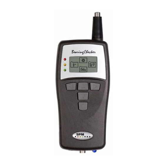
11 Serial number label General description The Bearing Checker is a shock pulse meter based on the well proven SPM method for quick and easy identification of bearing faults. The instrument has a built-in microprocessor programmed to analyze shock pulse patterns from all types of ball and roller bearings and display evaluated information on the operating condition of the bearing. -
Page 7: Displays And Icons
Displays and icons Main display Bearing measurement Stethoscope Temperature function measurement General settings Bearing measurement Back/Return TLT test Listening Memory Input data Measurement Input dBi Temperature measurement Stethoscope function Back/Return Back/Return (or press the probe tip) Measure Volume (1 – 8) General settings Temperature Back... -
Page 8: Start Up
When using external probes, meas- uring is started manually by pressing the measuring key (6) while in the Bearing mode. The blue measuring LED (9) stops blinking when an SPM measuring cycle is completed. The green, yellow and red LEDs (4) beside the display indicate the bearing condition after an SPM measure- ment. -
Page 9: Batteries
Batteries The instrument is powered by two batteries type MN 1500 LR6. Alkaline or rechargeable batteries can be used. Please note that rechargeable batteries must be removed from the instrument before recharging. battery compartment is located at the back. Press and push the lid to open the compartment. -
Page 10: Settings
Settings Battery type Main display Alcaline or rechargeable batteries can be used in Bearing Checker. The battery type has no influence on instrument functionality or operation, but should be set for the battery status icon to correctly show battery level. From the Main display, press DOWN arrow key to enter the General Set- tings folder. -
Page 11: Accessories
Accessories EAR12 15288 15287 15286 15455 TRA73 TRA74 Accessories EAR12 Headphones with ear defenders TRA73 External transducer with probe TRA74 Transducer with quick connector for adapters CAB52 Measuring cable with slip-on connector for permanently installed transducers, 1,5 m 15286 Belt holder for external probe transducer 15287 Belt case for accessories 15288... -
Page 12: Shock Pulse Measurement
The Shock Pulse Method The Bearing Checker is based on the Shock Pulse Method. Measurements with the SPM method give an indirect measure of impact velocity, i.e. the difference in velocity between two bodies at the moment of impact. -
Page 13: Normalized Shock Pulse Values With Dbi
Normalized and unnormalized readings The Bearing Checker measures impact velocity over a large dynamic range. In order to simplify readout and evaluation, a logarithmic measuring unit is used: decibel shock value (dBsv). dBsv is the general measuring unit for shock pulses. By measuring the shock pulses from a bearing in dBsv a value for their magnitude is obtained, for instance 42 dBsv. -
Page 14: The Dbm/Dbc Technique
The dBm/dBc technique Life time The dBm/dBc technique has been successfully applied for more than 35 years and continues to be widely used. It is well suited for industrial condition monitoring, because it works with few, easy to understand in- and output data. Even on a logarithmic scale, there is normally a large, distinct difference between the maximum values from good and bad bearings. -
Page 15: Rules For Measuring Points
Rules for measuring points 1. Straight and short path The rules for the selection of SPM measuring points have a very practical purpose. We are trying to capture low energy signals which are getting weaker the farther they travel and the more they are bounced about inside a piece of metal. -
Page 16: Measuring Points, Examples
Measuring points, examples The following two pages show measuring points and pos- sible adapter or transducer installations. How to install measuring equipment is described in the SPM installation manual. Through hole for long adapter Figure A shows how a measuring point beneath a fan cover can be reached with a long adapter, through a hole in the cover. - Page 17 On large electric motors, the bearings are often mounted in housings which are welded or bolted to the motor shields. Because of the damping in the interface between the bush- ing and the shield, the measuring point should be on the bushing.
-
Page 18: Measuring Range
Adapters required! ference level make it easier to get readings from low speed bearings. Successful SPM monitoring has been carried out on bearings with dBi = –3 (54 rpm, shaft diameter 260 mm). Note that the dynamic measuring range decreases when dBi values get below 0. -
Page 19: Creating Acceptable Measuring Conditions
Creating acceptable measuring conditions Scraping, alignment Alignment Cavitation Gear tooth damage No interference Low level interference High level interference The clicking of valves, high pressure steam flow, mechanical rubbing, damaged or badly adjusted gears, and load shocks from machine operation can cause a general high shock level on the machine frame. This interference can mask the bearing signal in cases where he shock level measured outside of the bearing housings is as high or higher than the shock level on the bearing housings. -
Page 20: Measuring Intervals
Measuring intervals measure often Measuring personnel should know about: • lubricant type • maximum quantity • lubricating intervals 1-3 months several days, one week Unpredicted, very rapid damage development is rare. Normally, surface damage develops slowly, over a period of many months. These are the general guidelines for selecting the interval between periodic readings: •... -
Page 21: Shock Pulse Transducers
Shock pulse transducers Built-in transducer with probe Measuring points for the built-in probe should be clearly marked. Always measure in the same spot. In addition, the probe is used to measure elsewhere on the machine, in case it is necessary to search for other shock pulse sources such as pump cavitation or rubbing parts. - Page 22 Check that installed transducers and adapters are properly mounted (see the instruction on SPM installations) and in good condition. You cannot expect a useful signal by attaching the quick connect trans- ducer to a rusty lump of metal, or from a transducer that is rolling on the floor on the other side of a partition.
-
Page 23: Bearing Measurement
Bearing Measurement Input data shaft For a reading of bearing condition with Bearing Checker, you need diameter ø the initial value, dBi. If you do not know the bearing´s dBi, Bear- ing Checker will calculate and display the dBi given the rotational speed (rpm) and the shaft diameter. -
Page 24: Shock Pulse Measurement
- bad (≥35) Surface temperature is measured automatically when an yellow - caution (21–34) SPM measurement is made. To see the temperature read- green - good (≤ 20) ing, use LEFT/RIGHT arrow keys to activate the Return icon in the Bearing display, then press the UP arrow key to enter the Main display. -
Page 25: Transducer Line Test
When measuring shock pulses with external transducers, a Bearing measurement transducer line test (TLT) will automatically be made to check the quality of the signal transmission between transducer and instrument (the TLT value for the latest reading is always saved and is shown in the TLT window). Part of your signal will be lost in a poor transducer line, so your measuring results will be lower than they should be. If an SPM measurement is made with a poor transducer line, the instrument will display a TLT warning sign. Transducer Line Test To perform a transducer line test (TLT) manually, connect the external transducer to the instrument. From the Main display, press the UP arrow key to enter the Bearing folder, then use LEFT/RIGHT arrow keys to highlight the TLT icon. Press the... -
Page 26: Listening To The Shock Pulse Pattern
To listen to the shock pulse pattern after taking an SPM reading, connect your headphones to the output connector (7). From the Main display, press the UP arrow key to enter Bearing mode. -
Page 27: Evaluating The Bearing Condition
Evaluating the Bearing Condition Cross talk from Interference from Reading correct ? Check! other bearings mechanical shocks Measuring point? Installation ? Correct dBi ? dBm? Look, feel, check data. Interference Shock pulse source? Search! Bearing ? Interference? Signal pattern? Loose High maximum value parts? Look, listen. -
Page 28: Identifying The Shock Pulse Source
Identifying the shock pulse source Play, scraping Excessive play Cavitation Gear tooth damage Shock pulses are strongest close to the source. They spread through the material of all machine parts, but are dampened (loss of signal) with distance and when passing through interfaces in the material. •... -
Page 29: Shock Pulse Patterns - Condition Codes
Shock pulse patterns – condition codes The headphone is a means to verify and trace shock pulse sources. The signal from a bearing should be highest on the bearing housing. If you get a higher signal outside of the bearing housing (across an interface in the material), you are most likely measuring shock pulses from another bearing or some other source. -
Page 30: Typical Shock Pulse Patterns From Rolling Bearings
Typical shock pulse patterns from rolling bearings A shock pulse pattern is a sequence of either random or rhythmical strong pulses (dBm level) above a carpet of very rapid weaker pulses (dBc level). You have to be aware of: • the dBm value •... - Page 31 Signal from a damaged bearing The pattern shown is typical for damaged bearing surfaces: a dBm above 35 dB, a large gap between dBm and dBc, and a random pattern of strong pulses. The strength of the maximum value dBm indicates the degree of damage: 35 –...
- Page 32 Patterns from poorly lubricated bearings A high carpet value, very close to the maximum value, is typical for dry running bearings. The dBm does not always reach the red zone – typical for poor lubrication is that the gap between dBm and dBc is very small. If the signal is strongest on the bearing housing, it can have several causes: •...
- Page 33 Periodic bursts Periodic bursts are a typical interference signal, caused by rubbing between machine parts, e.g. shaft against bearing housing or seal. The burst occurs at an rpm related frequency. Rhythmical peaks Single, rhythmical peaks can be caused by load and pressure shocks which occur during the machine’s normal operation.
-
Page 34: Confirming Bearing Damage
Confirming bearing damage On receiving the typical bearing damage signal – high dBm, large difference between dBm and dBc, random peaks, strongest signal on the bearing housing – you must confirm one of the following causes for the reading: • tapping of loose parts against the bearing housing •... - Page 35 Readings on gear boxes Shock pulses can sometimes spread through a machine housing without significant damping. This means that the shock pulses from the bearing with the highest shock pulse level can, under unfavourable circumstances, inter- fere with the readings on all the other bearings. The problem is aggravated when the bearings are of dif- ferent sizes and rotating at different speeds, as in a gear box.
-
Page 36: Evaluation Flow Chart
Evaluation flow chart Good bearing condition, installation and lubrication. Locate the signal source. The reading can be caused by Adjacent to cross talk from other defective bearings or disturbances the bearing from other mechanical shocks. If possible, isolate the housing Where source of disturbance and test again. - Page 37 The reading drops but increases again within a few hours. Probable causes: If possible, lubricate Cause: bearing damage. • Bearing damage. the bearing and check the reading at Shorten measuring intervals to follow the progress of the Measure in shorter the same time.
-
Page 38: Temperature Measurement
Machine surface temperature is also measured automatically when an SPM measurement is made: To see the temperature reading after an SPM measurement, use LEFT/RIGHT arrow keys to activate the Return icon in the Bearing display, then press the UP arrow key to enter the Main display. Press the LEFT arrow key to enter Temperature mode and see the reading. -
Page 39: Using The Stethoscope Function
Using the Stethoscope Function The stethoscope function is useful for detecting machine sound irregularities, such as load shocks and scraping. Connect your headphones to the output connector (7). From the Main display, use the RIGHT arrow button to enter the Stethoscope mode. Hold the probe tip against the object. -
Page 40: Technical Specifications
Thermopile Sensor TPS 334/3161, built-in contact free IR-sensor Stethoscope Headphone mode: 8 level amplification Article no. BC100 Bearing Checker Accessories EAR12 Headphones with ear defenders TRA73 External transducer with probe TRA74 Transducer with quick connector for adapters CAB52 Measuring cable with slip-on connector for permanently installed transducers, 1,5 m... -
Page 41: Maintenance And Calibration
Once the life cycle of the product is over you can return it to your local SPM representative for correct treatment, or dispose of it together with your other electronic waste. - Page 42 SPM Follow-up form ........
Need help?
Do you have a question about the BC100 and is the answer not in the manual?
Questions and answers